Aviation safety depends on the reliable performance of braking systems to decelerate aircraft, maintain control during taxiing, and ensure secure engine run-ups. Modern aircraft brakes are sophisticated units that convert the kinetic energy of a landing or taxiing aircraft into heat through controlled friction. From simple single-disc systems on light trainers to complex multiple-disc carbon assemblies on transport-category jets, these components must withstand extreme thermal and mechanical stresses. Proper maintenance, accurate wear monitoring, and precise hydraulic servicing are essential to ensuring that these systems remain functional under the most demanding operational conditions.
Brake Inspection & Service
Brake inspection and service is important to keep these critical aircraft components fully functional at all times. There are many different brake systems on aircraft. Brake system maintenance is performed both while the brakes are installed on the aircraft and when the brakes are removed. The manufacturer’s instructions must always be followed to ensure proper maintenance.
On Aircraft Servicing
Inspection and servicing of aircraft brakes while installed on the aircraft is required. The entire brake system must be inspected in accordance with manufacturer’s instructions. Some common inspection items include: brake lining wear, air in the brake system, fluid quantity level, leaks, and proper bolt torque.
Lining Wear
Brake lining material is made to wear as it causes friction during application of the brakes. This wear must be monitored to ensure it is not worn beyond limits and sufficient lining is available for effective braking. The aircraft manufacturer gives specifications for lining wear in its maintenance information. The amount of wear can be checked while the brakes are installed on the aircraft.
Many brake assemblies contain a built-in wear indicator pin. Typically, the exposed pin length decreases as the linings wear, and a minimum length is used to indicate the linings must be replaced. Caution must be used as different assemblies may vary in how the pin is measured. On the Goodyear brake described above, the wear pin is measured where it protrudes through the nut of the automatic adjuster on the back side of the piston cylinder. [Figure 1]
 |
| Figure 1. Brake lining wear on a Goodyear brake is ascertained by measuring the wear pin of the automatic adjuster |
The Boeing brake illustrated in Figure 2 measures the length of the pin from the back of the pressure plate when the brakes are applied (dimension L). The manufacturer’s maintenance information must be consulted to ensure brake wear pin indicators on different aircraft are read correctly.
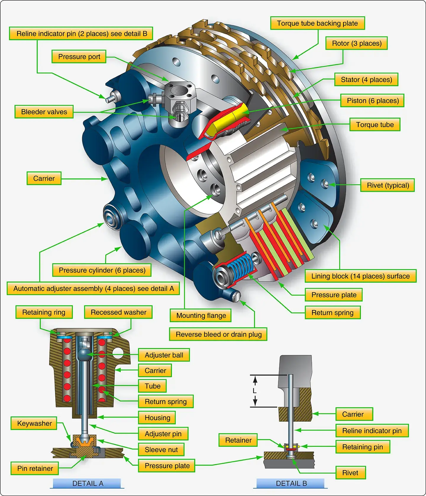 |
| Figure 2. The multiple-disk brake assembly and details from a Boeing 737 |
On many other brake assemblies, lining wear is not measured via a wear pin. The distance between the disc and a portion of the brake housing when the brakes are applied is sometimes used. As the linings wear, this distance increases. The manufacturer specifies at what distance the linings should be changed. [Figure 3]
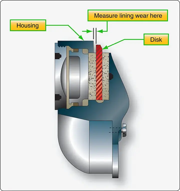 |
| Figure 3. The distance between the brake disc and the brake housing measured with the brakes applied is a means for determining brake lining wear on some brakes |
On Cleveland brakes, lining wear can be measured directly, since part of the lining is usually exposed. The diameter of a number 40 twist drill is approximately equal to the minimum lining thickness allowed. [Figure 4]
 |
| Figure 4. A #40 twist drill laid next to the brake lining indicates when the lining needs to be changed on a Cleveland brake |
Multiple disc brakes typically are checked for lining wear by applying the brakes and measuring the distance between the back of the pressure plate and the brake housing. [Figure 5] Regardless of the method particular to each brake, regular monitoring and measurement of brake wear ensures linings are replaced as they become unserviceable. Linings worn beyond limits usually require the brake assembly to be removed for replacement.
 |
| Figure 5. The distance between the brake housing and the pressure plate indicates lining wear on some multiple disc brakes |
Air in the Brake System
The presence of air in the brake system fluid causes the brake pedal to feel spongy. The air can be removed by bleeding to restore firm brake pedal feel. Brake systems must be bled according to manufacturers’ instructions. The method used is matched to the type of brake system. Brakes are bled by one of two methods: top-down gravity bleeding or bottom-up pressure bleeding. Brakes are bled when the pedals feel spongy or whenever the brake system has been opened.
Bleeding Master Cylinder Brake Systems
Brake systems with master cylinders may be bled by gravity or pressure bleeding methods. Follow the instructions in the aircraft maintenance manual. To pressure bleed a brake system from the bottom up, a pressure pot is used. [Figure 6] This is a portable tank that contains a supply of brake fluid under pressure. When dispersing fluid from the tank, pure air-free fluid is forced from near the bottom of the tank by the air pressure above it. The outlet hose that attaches the bleed port on the brake assembly contains a shut-off valve.Note that a similar source of pure, pressurized fluid can be substituted for a pressure tank, such as a hand-pump type unit found in some hangars.
 |
| Figure 6. A typical brake bleeder pot or tank contains pure brake fluid under pressure. It pushes the fluid through the brake system to displace any air that may be present |
The typical pressure bleed is accomplished as illustrated in Figure 7. The hose from the pressure tank is attached to the bleed port on the brake assembly. A clear hose is attached to the vent port on the aircraft brake fluid reservoir or on the master cylinder if it incorporates the reservoir. The other end of this hose is placed in a collection container with a supply of clean brake fluid covering the end of the hose. The brake assembly bleed port is opened. The valve on the pressure tank hose is then opened allowing pure, air-free fluid to enter the brake system. Fluid containing trapped air is expelled through the hose attached to the vent port of the reservoir. The clear hose is monitored for air bubbles. When they cease to exist, the bleed port and pressure tank shutoff are closed, and the pressure tank hose is removed. The hose at the reservoir is also removed. Fluid quantity may need to be adjusted to assure the reservoir is not over filled. Note that it is absolutely necessary that the proper fluid be used to service any brake system including when bleeding air from the brake lines.
 |
| Figure 7. Arrangement for bottom-up pressure bleeding of aircraft brakes. Fluid is pushed through the system until no air bubbles are visible in the hose at the top |
Brakes with master cylinders may also be gravity bled from the top down. This is a process similar to that used on automobiles. [Figure 8] Additional fluid is supplied to the aircraft brake reservoir so that the quantity does not exhaust while bleeding, which would cause the reintroduction of more air into the system. A clear hose is connected to the bleed port on the brake assembly. The other end is submersed in clean fluid in a container large enough to capture fluid expelled during the bleeding process. Depress the brake pedal and open the brake assembly bleed port. The piston in the master cylinder travels all the way to the end of the cylinder forcing air fluid mixture out of the bleed hose and into the container. With the pedal still depressed, close the bleed port. Pump the brake pedal to introduce more fluid from the reservoir ahead of the piston in the master cylinder. Hold the pedal down and open the bleed port on the brake assembly. More fluid and air is expelled through the hose into the container. Repeat this process until the fluid exiting the brake through the hose no longer contains any air. Tighten the bleed port fitting and ensure the reservoir is filled to the proper level.
 |
| Figure 8. Arrangement for top down or gravity bleeding of aircraft brakes |
Whenever bleeding the brakes, ensure that reservoirs and bleed tanks remain full during the process. Use only clean, specified fluid. Always check the brakes for proper operation, any leaks when bleeding is complete, and assure that the fluid quantity level is correct.
Bleeding Power Brake Systems
Top down brake bleeding is used in power brake systems. Power brakes are supplied with fluid from the aircraft hydraulic system. The hydraulic system should operate without air in the fluid as should the brake system. Therefore, bottom up pressure bleeding is not an option for power brakes. The trapped air in the brake system would be forced into the main hydraulic system, which is not acceptable.
Many aircraft with power brake systems accept the connection of an auxiliary hydraulic mule that can be used to establish pressure in the system for bleeding. Regardless, the aircraft system must be pressurized to bleed power brake systems. Attach a clear hose to the brake bleed port fitting on the brake assembly and immerse the other end of the hose in a container of clean hydraulic fluid. With the bleeder valve open, carefully apply the brake to allow aircraft hydraulic fluid to enter the brake system. The fluid expels the fluid contaminated with air out of the bleed hose into the container. When air is no longer visible in the hose, close the bleed valve and restore the hydraulic system to normal operation configuration.
Power brake systems on different aircraft contain many variations and a wide array of components that may affect the proper bleeding technique to be followed. Consult the manufacturer’s maintenance information for the correct bleeding procedure for each aircraft. Be sure to bleed auxiliary and emergency brake systems when bleeding the normal brake system to ensure proper operation when needed.
Fluid Quantity and Type
As mentioned, it is imperative that the correct hydraulic fluid is used in each brake system. Seals in the brake system are designed for a particular hydraulic fluid. Deterioration and failure occurs when they are exposed to other fluids. Mineral-based fluid, such as MIL-H-5606 (red oil), should never be mixed with phosphate-ester based synthetic hydraulic fluid, such as Skydrol®. Contaminated brake/hydraulic systems must have all of the fluid evacuated and all seals replaced before the aircraft is released for flight.
Fluid quantity is also important. The technician is responsible for determining the method used to ascertain when the brake and hydraulic systems are fully serviced and for the maintenance of the fluid at this level. Consult the manufacturer’s specifications for this information.
Inspection for Leaks
Aircraft brake systems should maintain all fluid inside lines and components and should not leak. Any evidence of a leak must be investigated for its cause. It is possible that the leak is a precursor to more significant damage that can be repaired, thus avoiding an incident or accident. [Figure 9]
 |
| Figure 9. The cause of all aircraft brake leaks must be investigated, repaired, and tested before releasing the aircraft for flight |
Many leaks are found at brake system fittings. While this type of leak may be fixed by tightening an obviously loose connection, the technician is cautioned against over-tightening fittings. Removal of hydraulic pressure from the brake system followed by disconnection and inspection of the connectors is recommended. Over-tightening of fitting can cause damage and make the leak worse. MS flareless fittings are particularly sensitive to over-tightening. Replace all fittings suspected of damage. Once any leak is repaired, the brake system must be re-pressurized and tested for function as well as to ensure the leak no longer exists. Occasionally, a brake housing may seep fluid through the housing body. Consult the manufacturer’s maintenance manual for limits and remove any brake assembly that seeps excessively.
Proper Bolt Torque
The stress experienced by the landing gear and brake system requires that all bolts are properly torqued. Bolts used to attach the brakes to the strut typically have the required torque specified in the manufacturer’s maintenance manual. Check for torque specifications that may exist for any landing gear and brake bolts, and ensure they are properly tightened. Whenever applying torque to a bolt on an aircraft, use of a calibrated torque wrench is required.
Off Aircraft Brake Servicing and Maintenance
Certain servicing and maintenance of an aircraft brake assembly is performed while it has been removed from the aircraft. A close inspection of the assembly and its many parts should be performed at this time. Some of the inspection items on a typical assembly follow.
Bolt and Threaded Connections
All bolts and threaded connections are inspected. They should be in good condition without signs of wear. Self-locking nuts should still retain their locking feature. The hardware should be what is specified in the brake manufacturer’s parts manual. Many aircraft brake bolts, for example, are not standard hardware and may be of closer tolerance or made of a different material. The demands of the high stress environment in which the brakes perform may cause brake failure if improper substitute hardware is used. Be sure to check the condition of all threads and O-ring seating areas machined into the housing. The fittings threaded into the housing must also be checked for condition.
Discs
Brake discs must be inspected for condition. Both rotating and stationary discs in a multiple disc brake can wear. Uneven wear can be an indication that the automatic adjusters may not be pulling the pressure plate back far enough to relieve all pressure on the disc stack.
Stationary discs are inspected for cracks. Cracks usually extend from the relief slots, if so equipped. On multiple disc brakes, the slots that key the disc to the torque tube must also be inspected for wear and widening. The discs should engage the torque tube without binding. The maximum width of the slots is given in the maintenance manual. Cracks or excessive key slot wear are grounds for rejection. Brake wear pads or linings must also be inspected for wear while the brake assembly is removed from the aircraft. Signs of uneven wear should be investigated, and the problem corrected. The pads may be replaced if worn beyond limits as long as the stationary disc upon which they mount passes inspection. Follow the manufacturer’s procedures for inspections and for pad replacement.
Rotating discs must be similarly inspected. The general condition of the disc must be observed. Glazing can occur when a disc or part of a disc is overheated. It causes brake squeal and chatter. It is possible to resurface a glazed disc if the manufacturer allows it. Rotating discs must also be inspected in the drive key slot or drive tang area for wear and deformation. Little damage is allowed before replacement is required.
The pressure plate and back plate on multiple disc brakes must be inspected for freedom of movement, cracks, general condition, and warping. New linings may be riveted to the plates if the old linings are worn and the condition of the plate is good. Note that replacing brake pads and linings by riveting may require specific tools and technique as described in the maintenance manual to ensure secure attachment. Minor warping can be straightened on some brake assemblies.
Automatic Adjuster Pins
A malfunctioning automatic adjuster assembly can cause the brakes to drag on the rotating disc(s) by not fully releasing and pulling the lining away from the disc. This can lead to excessive, uneven lining wear and disc glazing. The return pin must be straight with no surface damage so it can pass through the grip without binding. Damage under the head can weaken the pin and cause failure. Magnetic inspection is sometimes used to inspect for cracks.
The components of the grip and tube assembly must be in good condition. Clean and inspect in accordance with the manufacturer’s maintenance instructions. The grip must move with the force specified and must move through its full range of travel.
Torque Tube
A sound torque tube is necessary to hold the brake assembly stable on the landing gear. General visual inspection should be made for wear, burrs, and scratches. Magnetic particle inspection is used to check for cracks. The key areas should be checked for dimension and wear. All limits of damage are referenced in the manufacturer’s maintenance data. The torque tube should be replaced if a limit is exceeded.
Brake Housing and Piston Condition
The brake housing must be inspected thoroughly. Scratches, gouges, corrosion, or other blemishes may be dressed out and the surface treated to prevent corrosion. Minimal material should be removed when doing so. Most important is that there are no cracks in the housing. Fluorescent dye penetrant is typically used to inspect for cracks. If a crack is found, the housing must be replaced. The cylinder area(s) of the housing must be dimensionally checked for wear. Limits are specified in the manufacturer’s maintenance manual.
The brake pistons that fit into the cylinders in the housing must also be checked for corrosion, scratches, burrs, etc. Pistons are also dimensionally checked for wear limits specified in the maintenance data. Some pistons have insulators on the bottom. They should not be cracked and should be of a minimal thickness. A file can be used to smooth out minor irregularities.
Seal Condition
Brake seals are very important. Without properly functioning seals, brake operation will be compromised, or the brakes will fail. Over time, heat and pressure mold a seal into the seal groove and harden the material. Eventually, resilience is reduced and the seal leaks. New seals should be used to replace all seals in the brake assembly. Acquire seals by part number in a sealed package from a reputable supplier to avoid bogus seals and ensure the correct seals for the brake assembly in question. Check to ensure the new seals have not exceeded their shelf life, which is typically three years from the cure date.
Many brakes use back-up rings in the seal groove to support the O-ring seals and reduce the tendency of the seal to extrude into the space which it is meant to seal. These are often made of Teflon® or similar material. Back-up seals are installed on the side of the O-ring away from the fluid pressure. [Figure 10] They are often reusable.
 |
| Figure 10. Back-up rings are used to keep O-rings from extruding into the space between the piston and the cylinder. They are positioned on the side of the O-ring away from the fluid pressure |
Replacement of Brake Linings
In general aviation, replacement of brake linings is commonly done in the hangar. The general procedure used on two common brake assemblies is given. Follow the manufacturer’s instructions when replacing brake linings on any aircraft brake assembly.
Goodyear Brakes
To replace the linings on a Goodyear single disc brake assembly, the aircraft must be jacked and supported. Detach the anti-rattle clips that help center the disc in the wheel before removing the wheel from the axle. The disc remains between the inner and outer lining when the wheel is removed. Extract the disc to provide access to the old lining pucks. These can be removed from the cavities in the housing and replaced with new pucks. Ensure the smooth braking surface of the puck contacts the disc. Reinsert the disc between the linings. Reinstall the wheel and anti-rattle clips. Tighten the axle nut in accordance with the manufacturer’s instructions. Secure it with a cotter pin and lower the aircraft from the jack. [Figure 11]
 |
| Figure 11. Goodyear brake lining replacement requires that the wheel be removed from the axle to access the brake assembly. The lining pucks slip into recesses in the brake housing |
Cleveland Brakes
The popular Cleveland brake uniquely features the ability to change the brake linings without jacking the aircraft or removing the wheel. On these assemblies, the torque plate is bolted to the strut while the remainder of the brake is assembled on the anchor bolts. The disc rides between the pressure plate and back plate. Linings are riveted to both plates. By unbolting the cylinder housing from the backplate, the backplate is freed to drop away from the torque plate. The remainder of the assembly is pulled away, and the pressure plate slides off of the torque bolts. [Figure 12]
 |
| Figure 12. A Cleveland brake disassembles once the four bolts holding the cylinder to the backplate are removed while the aircraft wheel remains in place. The pressure plate slides off the anchor bolts and linings can be replaced by riveting on the pressure plate and back plate |
The rivets that hold the linings on the pressure plate and back plate are removed with a knockout punch. After a thorough inspection, new linings are riveted to the pressure plate and backplate using a rivet clinching tool [Figure 13] Kits are sold that supply everything needed to perform the operation. The brake is reassembled in the reverse order. Be certain to include any shims if required. The bolts holding the backplate to the cylinder assembly must be torqued according to manufacturer specifications and safetied. The manufacturer’s data also provides a burn-in procedure. The aircraft is taxied at a specified speed, and the brakes are smoothly applied. After a cooling period, the process is repeated, thus preparing the linings for service.
 |
| Figure 13. Rivet setting tool is used to install brake linings on Cleveland brake pressure plates and back plates |
Brake Malfunctions and Damage
Aircraft brakes operate under extreme stress and varied conditions. They are susceptible to malfunction and damage. A few common brake problems are discussed in this section.
Overheating
While aircraft brakes slow the aircraft by changing kinetic energy into heat energy, overheating of the brakes is not desirable. Excessive heat can damage and distort brake parts weakening them to the point of failure. Protocol for brake usage is designed to prevent overheating. When a brake shows signs of overheating, it must be removed from the aircraft and inspected for damage. When an aircraft is involved in an aborted takeoff, the brakes must be removed and inspected to ensure they withstood this high level of use.
The typical post-overheat brake inspection involves removal of the brake from the aircraft and disassembly of the brakes. All of the seals must be replaced. The brake housing must be checked for cracks, warping, and hardness per the maintenance manual. Any weakness or loss of heat treatment could cause the brake to fail under high-pressure braking. The brake discs must also be inspected. They must not be warped, and the surface treatment must not be damaged or transferred to an adjacent disc. Once reassembled, the brake should be bench tested for leaks and pressure tested for operation before being installed on the aircraft.
Dragging
Brake drag is a condition caused by the linings not retracting from the brake disc when the brakes are no longer being applied. It can be caused by several different factors. Brakes that drag are essentially partially on at all times. This can cause excessive lining wear and overheating leading to damage to the disc(s).
A brake may drag when the return mechanism is not functioning properly. This could be due to a weak return spring, the return pin slipping in the auto adjuster pin grip, or similar malfunction. Inspect the auto adjuster(s) and return units on the brake when dragging is reported. An overheated brake that has warped the disc also causes brake drag. Remove the brake and perform a complete inspection as discussed in the previous section. Air in the brake fluid line can also cause brake drag. Heat causes the air to expand, which pushes the brake linings against the disc prematurely. If no damage has been caused when reported, bleed the brakes to remove the air from the system to eliminate the drag.
At all times, the technician should perform inspections to ensure the proper parts are used in the brake assembly. Improper parts, especially in the retraction/adjuster assemblies, can cause the brakes to drag.
Chattering or Squealing
Brakes may chatter or squeal when the linings do not ride smoothly and evenly along the disc. A warped disc(s) in a multiple brake disc stack produces a condition wherein the brake is actually applied and removed many times per minute. This causes chattering and, at high frequency, it causes squealing. Any misalignment of the disc stack out of parallel causes the same phenomenon. Discs that have been overheated may have damage to the surface layer of the disc. Some of this mix may be transferred to the adjacent disc resulting in uneven disc surfaces that also lead to chatter or squeal. In addition to the noise produced by brake chattering and squealing, vibration is caused that may lead to further damage of the brake and the landing gear system. The technician must investigate all reports of brake chattering and squealing.