The nosewheel on most aircraft is steerable from the flight deck via a nosewheel steering system. This allows the aircraft to be directed during ground operation. A few simple aircraft have nosewheel assemblies that caster. Such aircraft are steered during taxi by differential braking.
Small Aircraft Nosewheel Steering
Most small aircraft have steering capabilities through the use of a simple system of mechanical linkages connected to the rudder pedals. Push-pull tubes are connected to pedal horns on the lower strut cylinder. As the pedals are depressed, the movement is transferred to the strut piston axle and wheel assembly which rotates to the left or right. [Figure 1]
 |
| Figure 1. Nose wheel steering on a light aircraft often uses a push-pull rod system connected to the rudder pedals |
Large Aircraft Nosewheel Steering
Due to their mass and the need for positive control, large aircraft utilize a power source for nosewheel steering. Hydraulic power predominates. There are many different designs for large aircraft nose steering systems. Most share similar characteristics and components. Control of the steering is from the flight deck through the use of a small wheel, tiller, or joystick typically mounted on the left side wall. Switching the system on and off is possible on some aircraft. Mechanical, electrical, or hydraulic connections transmit the controller input movement to a steering control unit.
The control unit is a hydraulic metering or control valve. It directs hydraulic fluid under pressure to one or two actuators designed with various linkages to rotate the lower strut. An accumulator and relief valve, or similar pressurizing assembly, keeps fluid in the actuators and system under pressure at all times. This permits the steering actuating cylinders to also act as shimmy dampers. A follow-up mechanism consists of various gears, cables, rods, drums, and/or bell-crank, etc. It returns the metering valve to a neutral position once the steering angle has been reached. Many systems incorporate an input subsystem from the rudder pedals for small degrees of turns made while directing the aircraft at high speed during takeoff and landing. Safety valves are typical in all systems to relieve pressure during hydraulic failure so the nosewheel can swivel.
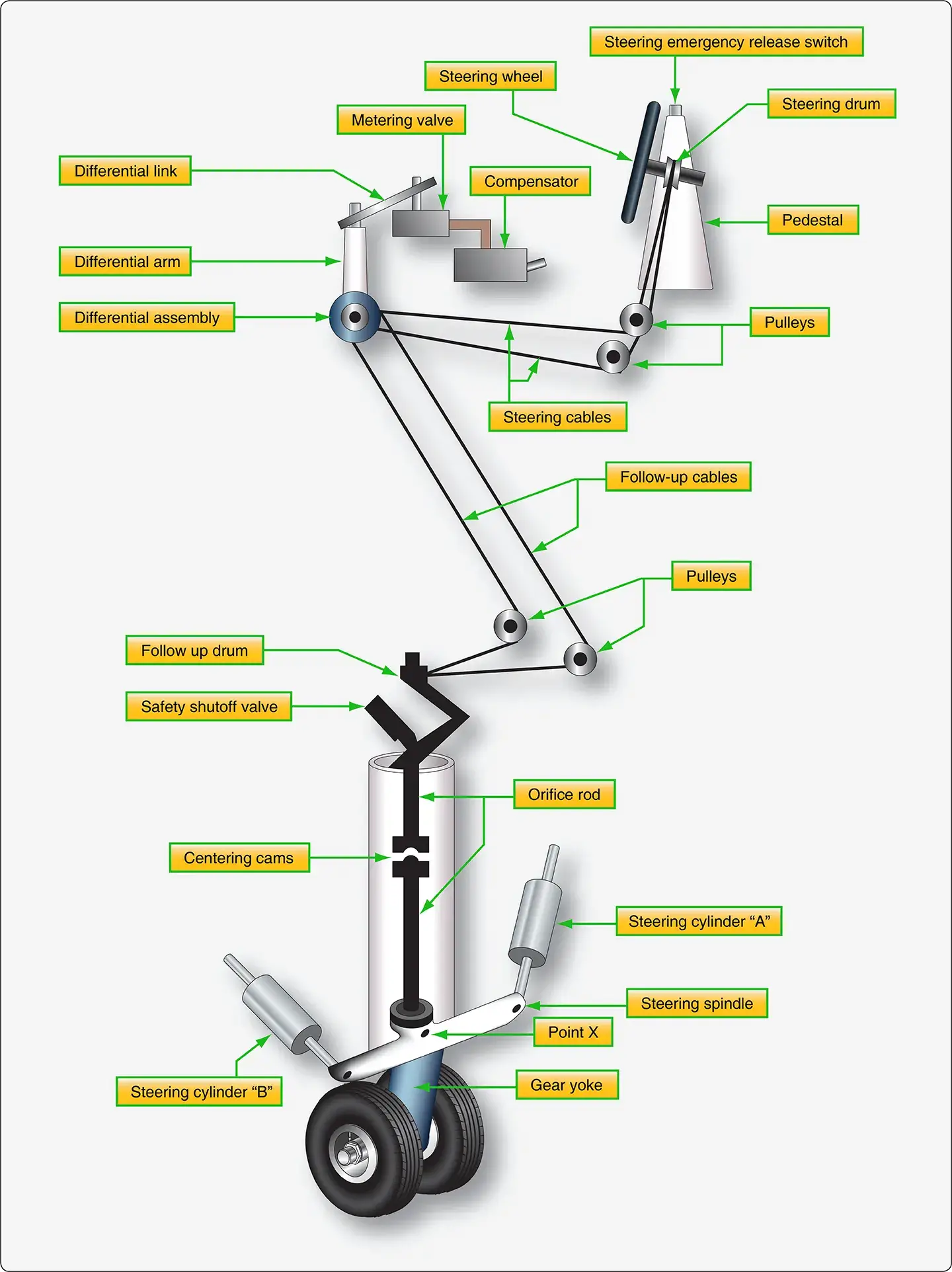
The following explanation accompanies Figures 2, 3, and 4, which illustrate a large aircraft nosewheel steering system and components. These figures and explanation are for instructional purposes only.
 |
| Figure 2. Example of a large aircraft hydraulic nose wheel steering system with hydraulic and mechanical units |
The nosewheel steering wheel connects through a shaft to a steering drum located inside the flight deck control pedestal. The rotation of this drum transmits the steering signal by means of cables and pulleys to the control drum of the differential assembly. Movement of the differential assembly is transmitted by the differential link to the metering valve assembly where it moves the selector valve to the selected position. This provides the hydraulic power for turning the nose gear.
 |
| Figure 3. Hydraulic system flow diagram of large aircraft nose wheel steering system |
As shown in Figure 3, pressure from the aircraft hydraulic system is directed through the open safety shutoff valve into a line leading to the metering valve. The metering valve then routes the pressurized fluid out of port A, through the right turn alternating line, and into steering cylinder A. This is a one-port cylinder and pressure forces the piston to begin extension. Since the rod of this piston connects to the nose steering spindle on the nose gear shock strut which pivots at point X, the extension of the piston turns the steering spindle gradually toward the right. As the nosewheel turns, fluid is forced out of steering cylinder B through the left turn alternating line and into port B of the metering valve. The metering valve directs this return fluid into a compensator that routes the fluid into the aircraft hydraulic system return manifold.
As described, hydraulic pressure starts the nose gear turning. However, the gear should not be turned too far. The nose gear steering system contains devices to stop the gear at the selected angle of turn and hold it there. This is accomplished with follow-up linkage. As stated, the nose gear is turned by the steering spindle as the piston of cylinder A extends. The rear of the spindle contains gear teeth that mesh with a gear on the bottom of the orifice rod. [Figure 2] As the nose gear and spindle turn, the orifice rod also turns but in the opposite direction. This rotation is transmitted by the two sections of the orifice rod to the scissor follow-up links located at the top of the nose gear strut. As the follow-up links return, they rotate the connected follow-up drum, which transmits the movement by cables and pulleys to the differential assembly. Operation of the differential assembly causes the differential arm and links to move the metering valve back toward the neutral position.
 |
| Figure 4. The metering valve and the compensator unit of the nose wheel steering system |
The metering valve and the compensator unit of the nosewheel steering system are illustrated in Figure 4. The compensator unit keeps fluid in the steering cylinders pressurized at all times. This hydraulic unit consists of a three-port housing that encloses a spring-loaded piston and poppet. The left port is an air vent that prevents trapped air at the rear of the piston from interfering with the movement of the piston. The second port located at the top of the compensator connects through a line to the metering valve return port. The third port is located at the right side of the compensator. This port connects to the hydraulic system return manifold. It routes the steering system return fluid into the manifold when the poppet valve is open.
The compensator poppet opens when pressure acting on the piston becomes high enough to compress the spring. In this system, 100 psi is required. Therefore, fluid in the metering valve return line is contained under that pressure. The 100 psi pressure also exists throughout the metering valve and back through the cylinder return lines. This pressurizes the steering cylinders at all times and permits them to function as shimmy dampers.
Shimmy Dampers
Torque links attached from the stationary upper cylinder of a nosewheel strut to the lower moveable cylinder or piston of the strut are not sufficient to prevent most nose gear from the tendency to oscillate rapidly, or shimmy, at certain speeds. This vibration must be controlled through the use of a shimmy damper. A shimmy damper controls nosewheel shimmy through hydraulic damping. The damper can be built integrally within the nose gear, but most often it is an external unit attached between the upper and lower shock struts. It is active during all phases of ground operation while permitting the nose gear steering system to function normally.
Steering Damper
As mentioned above, large aircraft with hydraulic steering hold pressure in the steering cylinders to provide the required damping. This is known as steering damping. Some older transport category aircraft have steering dampers that are vane-type. Nevertheless, they function to steer the nosewheel, as well as to dampen vibration.
Piston-Type
Aircraft not equipped with hydraulic nosewheel steering utilize an additional external shimmy damper unit. The case is attached firmly to the upper shock strut cylinder. The shaft is attached to the lower shock strut cylinder and to a piston inside the shimmy damper. As the lower strut cylinder tries to shimmy, hydraulic fluid is forced through a bleed hole in the piston. The restricted flow through the bleed hole dampens the oscillation. [Figure 5]
 |
| Figure 5. A shimmy damper on the nose strut of a small aircraft. The diagram shows the basic internal arrangement of most shimmy dampers. The damper in the photo is essentially the same except the piston shaft extends through both ends of the damper cylinder body |
A piston-type shimmy damper may contain a fill port to add fluid or it may be a sealed unit. Regardless, the unit should be checked for leaks regularly. To ensure proper operation, a piston-type hydraulic shimmy damper should be filled to capacity.
Vane-Type
A vane-type shimmy damper is sometimes used. [Figure 6] It uses fluid chambers created by the vanes separated by a valve orifice in a center shaft. As the nose gear tries to oscillate, vanes rotate to change the size of internal chambers filled with fluid. The chamber size can only change as fast as the fluid can be forced through the orifice. Thus, the gear oscillation is dissipated by the rate of fluid flow. An internal spring-loaded replenishing reservoir keeps pressurized fluid in the working chambers and thermal compensation of the orifice size is included. As with the piston type shimmy damper, the vane-type damper should be inspected for leaks and kept serviced. A fluid level indicator protrudes from the reservoir end of the unit.
 |
| Figure 6. A typical vane-type shimmy damper |
Non-Hydraulic Shimmy Damper
Non-hydraulic shimmy dampers are currently certified for many aircraft. They look and fit similar to piston-type shimmy dampers but contain no fluid inside. In place of the metal piston, a rubber piston presses out against the inner diameter of the damper housing when the shimmy motion is received through the shaft. The rubber piston rides on a very thin film of grease and the rubbing action between the piston and the housing provides the damping.
This is known as surface-effect damping. The materials used to construct this type of shimmy damper provide a long service life without the need to ever add fluid to the unit. [Figure 7]
 |
| Figure 7. A non-hydraulic shimmy damper uses a rubber piston with lubricant that dampens via motion against the inner diameter of the unit housing |