Aircraft landing gear retraction systems reduce drag and improve aircraft performance by retracting the landing gear into the fuselage or wing after takeoff. Light aircraft may use mechanical, electric, or electrohydraulic systems, while larger aircraft rely on hydraulic power, actuators, uplocks, downlocks, and sequence valves to ensure the gear and doors operate safely and in the correct order.
Small Aircraft Retraction Systems
As the speed of a light aircraft increases, there comes a point where the parasite drag created by the landing gear in the wind is greater than the induced drag caused by the added weight of a retractable landing gear system. Thus, many light aircraft have retractable landing gear. There are many unique designs. The simplest contains a lever in the flight deck mechanically linked to the gear. Through mechanical advantage, the pilot extends and retracts the landing gear by operating the lever. Use of a roller chain, sprockets, and a hand crank to decrease the required force is common.
Electrically operated landing gear systems are also found on light aircraft. An all-electric system uses an electric motor and gear reduction to move the gear. The rotary motion of the motor is converted to linear motion to actuate the gear. This is possible only with the relatively lightweight gear found on smaller aircraft. An all-electric gear retraction system is illustrated in Figure 1.
 |
| Figure 1. A geared electric motor landing gear retraction system |
A more common use of electricity in gear retraction systems is that of an electric/hydraulic system found in many Cessna and Piper aircraft. This is also known as a power pack system. A small lightweight hydraulic power pack contains several components required in a hydraulic system. These include the reservoir, a reversible electric motor-driven hydraulic pump, a filter, high- and low-pressure control valves, a thermal relief valve, and a shuttle valve. Some power packs incorporate an emergency hand pump. A hydraulic actuator for each gear is driven to extend or retract the gear by fluid from the power pack. Figure 2 illustrates a power pack system while gear is being lowered.
 |
| Figure 2. A popular light aircraft gear retraction system that uses a hydraulic power pack in the gear down condition |
Figure 3 shows the same system while the gear is being raised.
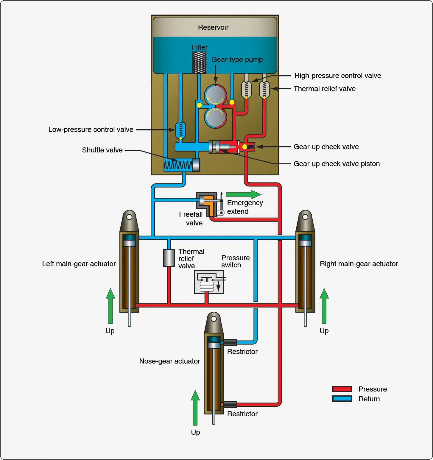 |
| Figure 3. A hydraulic power pack gear retraction system in the gear up condition |
When the flight deck gear selection handle is put in the gear-down position, a switch is made that turns on the electric motor in the power pack. The motor turns in the direction to rotate the hydraulic gear pump so that it pumps fluid to the gear-down side of the actuating cylinders. Pump pressure moves the spring-loaded shuttle valve to the left to allow fluid to reach all three actuators. Restrictors are used in the nose wheel actuator inlet and outlet ports to slow down the motion of this lighter gear. While hydraulic fluid is pumped to extend the gear, fluid from the upside of the actuators returns to the reservoir through the gear-up check valve. When the gear reach the down and locked position, pressure builds in the gear-down line from the pump and the low-pressure control valve unseats to return the fluid to the reservoir. Electric limit switches turn off the pump when all three gear are down and locked.
To raise the gear, the flight deck gear handle is moved to the gear-up position. This sends current to the electric motor, which drives the hydraulic gear pump in the opposite direction causing fluid to be pumped to the gear-up side of the actuators. In this direction, pump inlet fluid flows through the filter. Fluid from the pump flows through the gear-up check valve to the gear-up sides of the actuating cylinders.
As the cylinders begin to move, the pistons release the mechanical down locks that hold the gear rigid for ground operations. Fluid from the gear-down side of the actuators returns to the reservoir through the shuttle valve. When the three gears are fully retracted, pressure builds in the system, and a pressure switch is opened that cuts power to the electric pump motor. The landing gear is held in the retracted position with hydraulic pressure. If pressure declines, the pressure switch closes to run the pump and raise the pressure until the pressure switch opens again.
Large Aircraft Retraction Systems
Large aircraft retraction systems are nearly always powered by hydraulic systems. Typically, the hydraulic pump is driven off of the engine accessory drive. Auxiliary electric hydraulic pumps are also common. Other devices used in a hydraulically-operated retraction system include actuating cylinders, selector valves, uplocks, downlocks, sequence valves, priority valves, tubing, and other conventional hydraulic system components. These units are interconnected so that they permit properly sequenced retraction and extension of the landing gear and the landing gear doors.
The correct operation of any aircraft landing gear retraction system is extremely important. Figure 4 illustrates an example of a simple large aircraft hydraulic landing gear system. The system is on an aircraft that has doors that open before the gear is extended and close after the gear is retracted. The nose gear doors operate via mechanical linkage and do not require hydraulic power. There are many gear and gear door arrangements on various aircraft. Some aircraft have gear doors that close to fair the wheel well after the gear is extended. Others have doors mechanically attached to the outside of the gear so that when it stows inward, the door stows with the gear and fairs with the fuselage skin.
 |
| Figure 4. A simple large aircraft hydraulic gear retraction system |
In the system illustrated in Figure 4, when the flight deck gear selector is moved to the gear-up position, it positions a selector valve to allow pump pressure from the hydraulic system manifold to access eight different components. The three downlocks are pressurized and unlocked so the gear can be retracted. At the same time, the actuator cylinder on each gear also receives pressurized fluid to the gear-up side of the piston through an unrestricted orifice check valve. This drives the gear into the wheel well. Two sequence valves (C and D) also receive fluid pressure. Gear door operation must be controlled so that it occurs after the gear is stowed. The sequence valves are closed and delay flow to the door actuators.
When the gear cylinders are fully retracted, they mechanically contact the sequence valve plungers that open the valves and allow fluid to flow into the close side of the door actuator cylinders. This closes the doors. Sequence valves A and B act as check valves during retraction. They allow fluid to flow one way from the gear-down side of the main gear cylinders back into the hydraulic system return manifold through the selector valve.
To lower the gear, the selector is put in the gear-down position. Pressurized hydraulic fluid flows from the hydraulic manifold to the nose gear uplock, which unlocks the nose gear. Fluid flows to the gear-down side of the nose gear actuator and extends it. Fluid also flows to the open side of the main gear door actuators. As the doors open, sequence valves A and B block fluid from unlocking the main gear uplocks and prevent fluid from reaching the down side of the main gear actuators.
When the doors are fully open, the door actuator engages the plungers of both sequence valves to open the valves. The main gear uplocks then receive fluid pressure and unlock. The main gear cylinder actuators receive fluid on the down side through the open sequence valves to extend the gear. Fluid from each main gear cylinder up-side flows to the hydraulic system return manifold through restrictors in the orifice check valves. The restrictors slow the extension of the gear to prevent impact damage.
There are numerous hydraulic landing gear retraction system designs. Priority valves are sometimes used instead of mechanically operated sequence valves. This controls some gear component activation timing via hydraulic pressure. Particulars of any gear system are found in the aircraft maintenance manual. The aircraft technician must be thoroughly familiar with the operation and maintenance requirements of this crucial system.