 |
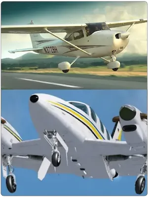
| Figure 1. Landing gear can be fixed (top) or retractable (bottom) |
Landing gear must be strong enough to withstand the forces of landing when the aircraft is fully loaded. In addition to strength, a major design goal is to have the gear assembly be as light as possible. To accomplish this, landing gear are made from a wide range of materials including steel, aluminum, and magnesium. Wheels and tires are designed specifically for aviation use and have unique operating characteristics. Main wheel assemblies usually have a braking system. To aid with the potentially high impact of landing, most landing gear have a means of either absorbing shock or accepting shock and distributing it so that the structure is not damaged.
Not all aircraft landing gear are configured with wheels. Helicopters, for example, have such high maneuverability and low landing speeds that a set of fixed skids is common and quite functional with lower maintenance. The same is true for free balloons which fly slowly and land on wood skids affixed to the floor of the gondola. Other aircraft landing gear are equipped with pontoons or floats for operation on water. A large amount of drag accompanies this type of gear, but an aircraft that can land and take off on water can be very useful in certain environments. Even skis can be found under some aircraft for operation on snow and ice. Figure 2 shows some of these alternative landing gear, the majority of which are the fixed gear type.
 |
| Figure 2. Aircraft landing gear without wheels |
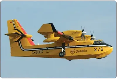
Amphibious aircraft are aircraft than can land either on land or on water. On some aircraft designed for such dual usage, the bottom half of the fuselage acts as a hull. Usually, it is accompanied by outriggers on the underside of the wings near the tips to aid in water landing and taxi. Main gear that retract into the fuselage are only extended when landing on the ground or a runway. This type of amphibious aircraft is sometimes called a flying boat. [Figure 3]
 |
| Figure 3. An amphibious aircraft is sometimes called a flying boat because the fuselage doubles as a hull |
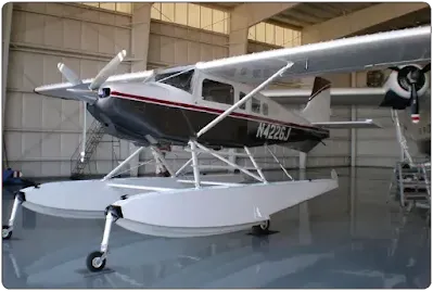
Many aircraft originally designed for land use can be fitted with floats with retractable wheels for amphibious use. [Figure 4] Typically, the gear retracts into the float when not needed. Sometimes a dorsal fin is added to the aft underside of the fuselage for longitudinal stability during water operations. It is even possible on some aircraft to direct this type of fin by tying its control into the aircraft’s rudder pedals. Skis can also be fitted with wheels that retract to allow landing on solid ground or on snow and ice.
 |
| Figure 4. Retractable wheels make this aircraft amphibious |
Tail Wheel Gear Configuration
There are two basic configurations of airplane landing gear: conventional gear or tail wheel gear and the tricycle gear. Tail wheel gear dominated early aviation and therefore has become known as conventional gear. In addition to its two main wheels which are positioned under most of the weight of the aircraft, the conventional gear aircraft also has a smaller wheel located at the aft end of the fuselage. [Figure 5] Often this tail wheel is able to be steered by rigging cables attached to the rudder pedals. Other conventional gear have no tail wheel at all using just a steel skid plate under the aft fuselage instead. The small tail wheel or skid plate allows the fuselage to incline, thus giving clearance for the long propellers that prevailed in aviation through WWII. It also gives greater clearance between the propeller and loose debris when operating on an unpaved runway. But the inclined fuselage blocks the straight ahead vision of the pilot during ground operations. Until up to speed where the elevator becomes effective to lift the tail wheel off the ground, the pilot must lean his head out the side of the cockpit to see directly ahead of the aircraft.
 |
| Figure 5. An aircraft with tail wheel gear |
The use of tail wheel gear can pose another difficulty. When landing, tail wheel aircraft can easily ground loop. A ground loop is when the tail of the aircraft swings around and comes forward of the nose of the aircraft. The reason this happens is due to the two main wheels being forward of the aircraft’s center of gravity. The tail wheel is aft of the center of gravity. If the aircraft swerves upon landing, the tail wheel can swing out to the side of the intended path of travel. If far enough to the side, the tail can pull the center of gravity out from its desired location slightly aft of but between the main gear. Once the center of gravity is no longer trailing the mains, the tail of the aircraft freely pivots around the main wheels causing the ground loop.
Conventional gear is useful and is still found on certain models of aircraft manufactured today, particularly aerobatic aircraft, crop dusters, and aircraft designed for unpaved runway use. It is typically lighter than tricycle gear which requires a stout, fully shock absorbing nose wheel assembly. The tail wheel configuration excels when operating out of unpaved runways. With the two strong main gear forward providing stability and directional control during takeoff roll, the lightweight tail wheel does little more than keep the aft end of the fuselage from striking the ground. As mentioned, at a certain speed, the air flowing over the elevator is sufficient for it to raise the tail off the ground. As speed increases further, the two main wheels under the center of gravity are very stable.
Tricycle Gear Configuration
Tricycle gear is the most prevalent landing gear configuration in aviation. In addition to the main wheels, a shock absorbing nose wheel is at the forward end of the fuselage. Thus, the center of gravity is then forward of the main wheels. The tail of the aircraft is suspended off the ground and clear view straight ahead from the cockpit is given. Ground looping is nearly eliminated since the center of gravity follows the directional nose wheel and remains between the mains.
Light aircraft use tricycle gear, as well as heavy aircraft. Twin nose wheels on the single forward strut and massive multistrut/ multiwheel main gear may be found supporting the world’s largest aircraft, but the basic configuration is still tricycle. The nose wheel may be steered with the rudder pedals on small aircraft. Larger aircraft often have a nose wheel steering wheel located off to the side of the cockpit. Figure 6 shows aircraft with tricycle gear. Aircraft Landing Gear Systems, discusses landing gear in detail.
 |
| Figure 6. Tricycle landing gear is the most predominant landing gear configuration in aviation |
 |
| Watch on YouTube |
RELATED POSTS