Flight control surfaces are aerodynamic devices that enable a pilot to control an aircraft's attitude and direction during flight. By altering the airflow around the aircraft, these surfaces produce forces and moments that allow movement about the three axes of flight. The primary flight control surfaces include the ailerons, elevator, and rudder, while some aircraft use dual-purpose control surfaces that combine multiple control functions into a single aerodynamic surface.
Primary Flight Control Surfaces
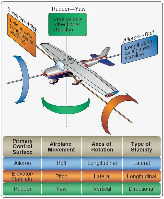
The primary flight control surfaces on a fixed-wing aircraft include: ailerons, elevators, and the rudder. The ailerons are attached to the trailing edge of both wings and when moved, rotate the aircraft around the longitudinal axis. The elevator is attached to the trailing edge of the horizontal stabilizer.
When it is moved, it alters aircraft pitch, which is the attitude about the horizontal or lateral axis. The rudder is hinged to the trailing edge of the vertical stabilizer. When the rudder changes position, the aircraft rotates about the vertical axis (yaw). Figure 1 shows the primary flight controls of a light aircraft and the movement they create relative to the three axes of flight.
 |
| Figure 1. Flight control surfaces move the aircraft around the three axes of flight |
Primary control surfaces are usually similar in construction to one another and vary only in size, shape, and methods of attachment. On aluminum light aircraft, their structure is often similar to an all-metal wing. This is appropriate because the primary control surfaces are simply smaller aerodynamic devices.
They are typically made from an aluminum alloy structure built around a single spar member or torque tube to which ribs are fitted and a skin is attached. The lightweight ribs are, in many cases, stamped out from flat aluminum sheet stock. Holes in the ribs lighten the assembly. An aluminum skin is attached with rivets. Figure 2 illustrates this type of structure, which can be found on the primary control surfaces of light aircraft as well as on medium and heavy aircraft.
 |
| Figure 2. Typical structure of an aluminum flight control surface |
Primary control surfaces constructed from composite materials are also commonly used. These are found on many heavy and high-performance aircraft, as well as gliders, home-built, and light-sport aircraft. The weight and strength advantages over traditional construction can be significant. A wide variety of materials and construction techniques are employed. Figure 3 shows examples of aircraft that use composite technology on primary flight control surfaces.
 |
| Figure 3. Composite control surfaces and some of the many aircraft that utilize them |
Note that the control surfaces of fabric-covered aircraft often have fabric-covered surfaces just as aluminum-skinned (light) aircraft typically have all-aluminum control surfaces. There is a critical need for primary control surfaces to be balanced so they do not vibrate or flutter in the wind.
Performed to manufacturer’s instructions, balancing usually consists of assuring that the center of gravity of a particular device is at or forward of the hinge point. Failure to properly balance a control surface could lead to catastrophic failure. Figure 4 illustrates several aileron configurations with their hinge points well aft of the leading edge. This is a common design feature used to prevent flutter.
 |
| Figure 4. Aileron hinge locations are very close to but aft of the center of gravity to prevent flutter |
Ailerons
Ailerons are the primary flight control surfaces that move the aircraft about the longitudinal axis. In other words, movement of the ailerons in flight causes the aircraft to roll. Ailerons are usually located on the outboard trailing edge of each of the wings. They are built into the wing and are calculated as part of the wing’s surface area. Figure 5 shows aileron locations on various wing tip designs.
 |
| Figure 5. Aileron location on various wings |
Ailerons are controlled by a side-to-side motion of the control stick in the flight deck or a rotation of the control yoke. When the aileron on one wing deflects down, the aileron on the opposite wing deflects upward. This amplifies the movement of the aircraft around the longitudinal axis. On the wing on which the aileron trailing edge moves downward, camber is increased, and lift is increased. Conversely, on the other wing, the raised aileron decreases lift. [Figure 6] The result is a sensitive response to the control input to roll the aircraft.
 |
| Figure 6. Differential aileron control movement. When one aileron is moved down, the aileron on the opposite wing is deflected upward |
The pilot’s request for aileron movement and roll is transmitted from the flight deck to the actual control surface in a variety of ways depending on the aircraft. A system of control cables and pulleys, push-pull tubes, hydraulics, electric, or a combination of these can be employed. [Figure 7]
 |
| Figure 7. Transferring control surface inputs from the cockpit |
Simple, light aircraft usually do not have hydraulic or electric fly-by-wire aileron control. These are found on heavy and high-performance aircraft. Large aircraft and some high-performance aircraft may also have a second set of ailerons located inboard on the trailing edge of the wings. These are part of a complex system of primary and secondary control surfaces used to provide lateral control and stability in flight.
At low speeds, the ailerons may be augmented by the use of flaps and spoilers. At high speeds, only inboard aileron deflection is required to roll the aircraft while the other control surfaces are locked out or remain stationary. Figure 8 illustrates the location of the typical flight control surfaces found on a transport category aircraft.
 |
| Figure 8. Typical flight control surfaces on a transport category aircraft |
Elevator
The elevator is the primary flight control surface that moves the aircraft around the horizontal or lateral axis. This causes the nose of the aircraft to pitch up or down. The elevator is hinged to the trailing edge of the horizontal stabilizer and typically spans most or all of its width. It is controlled from the flight deck by pushing or pulling the control stick or control yoke forward or aft.
Light aircraft use a system of control cables and pulleys or push-pull tubes to transfer flight deck inputs to the movement of the elevator. High-performance and large aircraft typically employ more complex systems. Hydraulic power is commonly used to move the elevator on these aircraft. On aircraft equipped with fly-by-wire controls, a combination of electrical and hydraulic power is used.
Rudder
The rudder is the primary control surface that causes an aircraft to yaw or move about the vertical axis. This provides directional control and thus points the nose of the aircraft in the direction desired. Most aircraft have a single rudder hinged to the trailing edge of the vertical stabilizer. It is controlled by a pair of foot-operated rudder pedals in the flight deck. When the right pedal is pushed forward, it deflects the rudder to the right, which moves the nose of the aircraft to the right. The left pedal is rigged to simultaneously move aft. When the left pedal is pushed forward, the nose of the aircraft moves to the left.
As with the other primary flight controls, the transfer of the movement of the flight deck controls to the rudder varies with the complexity of the aircraft. Many aircraft incorporate the directional movement of the nose or tail wheel into the rudder control system for ground operation. This allows the operator to steer the aircraft with the rudder pedals during taxi when the airspeed is not high enough for the control surfaces to be effective.
Some large aircraft have a split rudder arrangement. This is actually two rudders, one above the other. At low speeds, both rudders deflect in the same direction when the pedals are pushed. At higher speeds, one of the rudders becomes inoperative as the deflection of a single rudder is aerodynamically sufficient to maneuver the aircraft.
Dual Purpose Flight Control Surfaces
The ailerons, elevators, and rudder are considered conventional primary control surfaces. However, some aircraft are designed with a control surface that may serve a dual purpose. For example, elevons perform the combined functions of the ailerons and the elevator. [Figure 9]
 |
| Figure 9. Elevons |
A movable horizontal tail section, called a stabilator, is a control surface that combines the functions of both the horizontal stabilizer and the elevator. Unlike a conventional tail arrangement, the entire stabilator pivots to control aircraft pitch. [Figure 10]
 |
| Figure 10. A stabilizer and index marks on a transport category aircraft |
A ruddervator combines the action of the rudder and elevator. [Figure 11]
 |
| Figure 11. Ruddervator |
This is possible on aircraft with V–tail empennages where the traditional horizontal and vertical stabilizers do not exist. Instead, two stabilizers angle upward and outward from the aft fuselage in a “V” configuration. Each contains a movable ruddervator built into the trailing edge. Movement of the ruddervators can alter the movement of the aircraft around the horizontal and/or vertical axis. Additionally, some aircraft are equipped with flaperons. [Figure 12]
 |
| Figure 12. Flaperons |
Flaperons are control surfaces that combine the functions of both ailerons and flaps. Flaps are secondary control surfaces on most wings, discussed in the Secondary or Auxiliary Control Surfaces section.
Quick Review: Primary Flight Control Surfaces
How do ailerons manipulate airflow to cause an aircraft to roll?
Why is balancing primary flight control surfaces considered safety-critical?
How do transport category aircraft utilize ailerons differently at high speeds?
What are some examples of dual-purpose flight control surfaces?
- Elevons: Combine the functions of ailerons and elevators (common on delta-wing aircraft).
- Ruddervators: Combine rudder and elevator functions on V-tail aircraft.
- Flaperons: Serve as both ailerons for roll control and flaps for lifting performance.
- Stabilators: An all-moving horizontal tail that acts as both a stabilizer and an elevator.