Aircraft wings are the primary lifting surfaces of an aircraft and are designed to provide the strength, stability, and aerodynamic characteristics required for flight. Wing construction varies according to the aircraft’s size, performance requirements, and intended use, but most wings share common structural elements such as spars, ribs, stringers, and skin. Understanding wing configurations, structural components, and nacelle construction is essential for aircraft maintenance personnel and aviation professionals.
Wing Configurations
Wings are airfoils that, when moved rapidly through the air, create lift. They are built in many shapes and sizes. Wing design can vary to provide certain desirable flight characteristics. Control at various operating speeds, the amount of lift generated, balance, and stability all change as the shape of the wing is altered.
Both the leading edge and the trailing edge of the wing may be straight or curved, or one edge may be straight and the other curved. One or both edges may be tapered so that the wing is narrower at the tip than at the root where it joins the fuselage. The wing tip may be square, rounded, or even pointed. Figure 1 shows a number of typical wing leading and trailing edge shapes.
 |
| Figure 1. Various wing design shapes yield different performance |
The wings of an aircraft can be attached to the fuselage at the top, mid-fuselage, or at the bottom. They may extend perpendicular to the horizontal plane of the fuselage or can angle up or down slightly. This angle is known as the wing dihedral. The dihedral angle affects the lateral stability of the aircraft. Figure 2 shows some common wing attach points and dihedral angle.
 |
| Figure 2. Wing attach points and wing dihedrals |
Wing Structure
The wings of an aircraft are designed to lift it into the air. Their particular design for any given aircraft depends on a number of factors, such as size, weight, use of the aircraft, desired speed in flight and at landing, and desired rate of climb. The wings of aircraft are designated left and right, corresponding to the left and right sides of the operator when seated in the flight deck. [Figure 3]
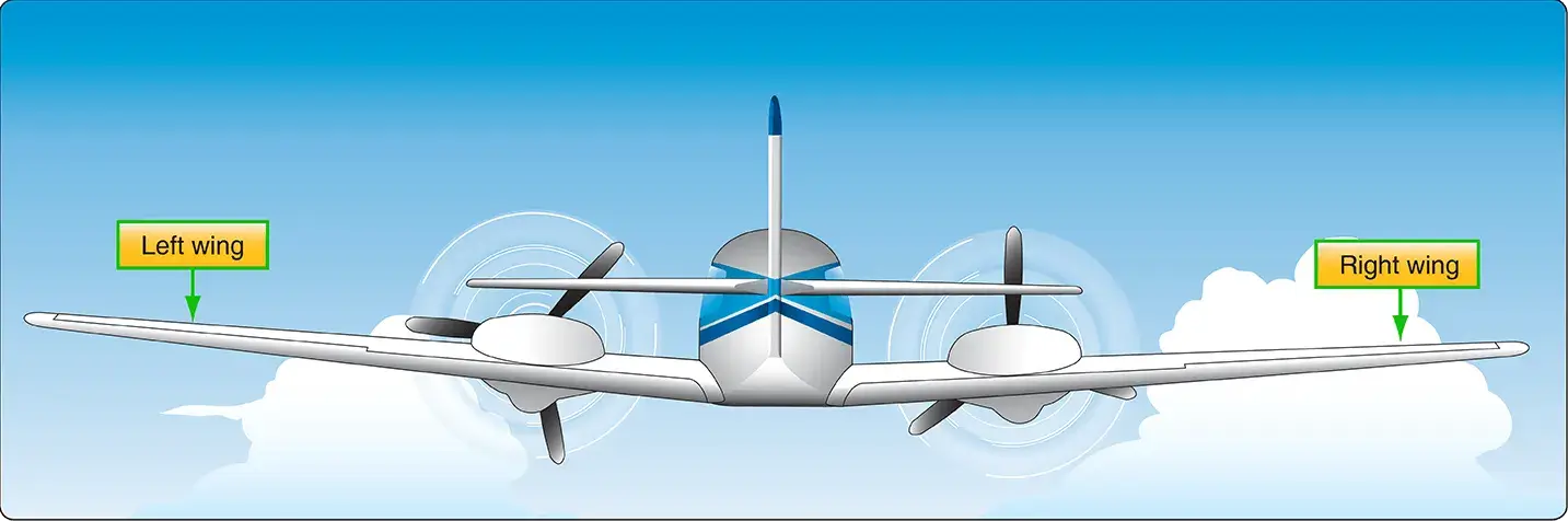 |
| Figure 3. “Left” and “right” on an aircraft are oriented to the perspective of a pilot sitting in the cockpit |
Often wings are of full cantilever design. This means they are built so that no external bracing is needed. They are supported internally by structural members assisted by the skin of the aircraft. Other aircraft wings use external struts or wires to assist in supporting the wing and carrying the aerodynamic and landing loads.
Wing support cables and struts are generally made from steel. Many struts and their attach fittings have fairings to reduce drag. Short, nearly vertical supports called jury struts are found on struts that attach to the wings a great distance from the fuselage. This serves to reduce strut movement and oscillation caused by the air flowing around the strut in flight. Figure 4 shows samples of wings using external bracing, also known as semicantilever wings. Cantilever wings built with no external bracing are also shown.
 |
| Figure 4. Externally braced wings, also called semicantilever wings, have wires or struts to support the wing. Full cantilever wings have no external bracing and are supported internally |
Aluminum is the most common material from which to construct wings, but they can be wood covered with fabric, and occasionally a magnesium alloy has been used. Moreover, modern aircraft are tending toward lighter and stronger materials throughout the airframe and in wing construction. Wings made entirely of carbon fiber or other composite materials exist, as well as wings made of a combination of materials for maximum strength to weight performance.
The internal structures of most wings are made up of spars and stringers running spanwise and ribs and formers or bulkheads running chordwise (leading edge to trailing edge). The spars are the principal structural members of a wing. They support all distributed loads, as well as concentrated weights such as the fuselage, landing gear, and engines. The skin, which is attached to the wing structure, carries part of the loads imposed during flight. It also transfers the stresses to the wing ribs. The ribs, in turn, transfer the loads to the wing spars. [Figure 5]
 |
| Figure 5. Wing structure nomenclature |
In general, wing construction is based on one of three fundamental designs:
- Monospar
- Multispar
- Box beam
Modification of these basic designs may be adopted by various manufacturers.
The monospar wing incorporates only one main spanwise or longitudinal member in its construction. Ribs or bulkheads supply the necessary contour or shape to the airfoil. Although the strict monospar wing is not common, this type of design modified by the addition of false spars or light shear webs along the trailing edge for support of control surfaces is sometimes used.
The multispar wing incorporates more than one main longitudinal member in its construction. To give the wing contour, ribs or bulkheads are often included.
The box beam type of wing construction uses two main longitudinal members with connecting bulkheads to furnish additional strength and to give contour to the wing. [Figure 6]
 |
| Figure 6. Box beam construction |
A corrugated sheet may be placed between the bulkheads and the smooth outer skin so that the wing can better carry tension and compression loads. In some cases, heavy longitudinal stiffeners are substituted for the upper surface of the wing and stiffeners on the lower surface corrugated sheets. A combination of corrugated sheets on the upper surface of the wing and stiffeners on the lower surface is sometimes used. Air transport category aircraft often utilize box beam wing construction.
Wing Spars
Spars are the principal structural members of the wing. They correspond to the longerons of the fuselage. They run parallel to the lateral axis of the aircraft, from the fuselage toward the tip of the wing, and are usually attached to the fuselage by wing fittings, plain beams, or a truss.
Spars may be made of metal, wood, or composite materials depending on the design criteria of a specific aircraft. Wooden spars are usually made from spruce. They can be generally classified into four different types by their cross-sectional configuration. As shown in Figure 7, they may be (A) solid, (B) box shaped, (C) partly hollow, or (D) in the form of an I-beam.
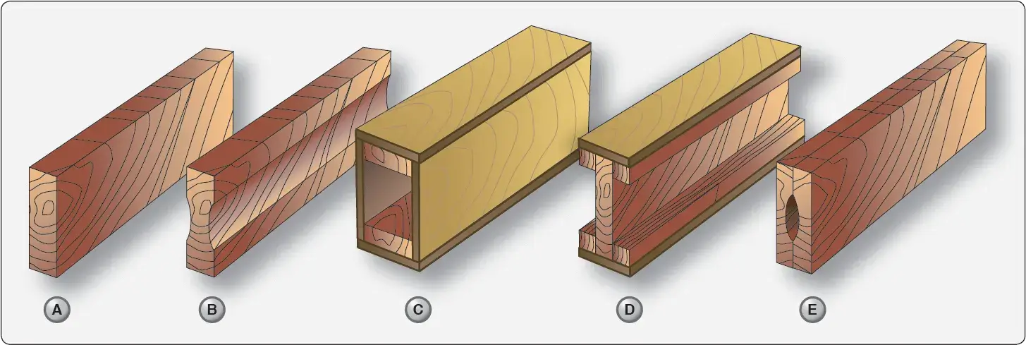 |
| Figure 7. Typical wooden wing spar cross-sections |
Lamination of solid wood spars is often used to increase strength. Laminated wood can also be found in box-shaped spars. The spar in Figure 7E has had material removed to reduce weight but retains the strength of a rectangular spar. As can be seen, most wing spars are basically rectangular in shape with the long dimension of the cross-section oriented up and down in the wing.
Currently, most manufactured aircraft have wing spars made of solid extruded aluminum or aluminum extrusions riveted together to form the spar. The increased use of composites and the combining of materials should make airmen vigilant for wing spars made from a variety of materials. Figure 8 shows examples of metal wing spar cross-sections.
 |
| Figure 8. Examples of metal wing spar shapes |
In an I–beam spar, the top and bottom of the I–beam are called the caps and the vertical section is called the web. The entire spar can be extruded from one piece of metal but often it is built up from multiple extrusions or formed angles. The web forms the principal depth portion of the spar and the cap strips (extrusions, formed angles, or milled sections) are attached to it. Together, these members carry the loads caused by wing bending, with the caps providing a foundation for attaching the skin. Although the spar shapes in Figure 8 are typical, actual wing spar configurations assume many forms.
For example, the web of a spar may be a plate or a truss as shown in Figure 9.
 |
| Figure 9. A truss wing spar |
It could be built up from lightweight materials with vertical stiffeners employed for strength. [Figure 10]
 |
| Figure 10. A plate web wing spar with vertical stiffeners |
It could also have no stiffeners but might contain flanged holes for reducing weight while maintaining strength. Some metal and composite wing spars retain the I-beam concept but use a sine wave web. [Figure 11]
 |
| Figure 11. A sine wave wing spar can be made from aluminum or composite materials |
Additionally, fail-safe spar web design exists. Fail-safe means that should one member of a complex structure fail, some other part of the structure assumes the load of the failed member and permits continued operation. A spar with fail-safe construction is shown in Figure 12.
 |
| Figure 12. A fail-safe spar with a riveted spar web |
This spar is made in two sections. The top section consists of a cap riveted to the upper web plate. The lower section is a single extrusion consisting of the lower cap and web plate. These two sections are spliced together to form the spar. If either section of this type of spar breaks, the other section can still carry the load. This is the fail-safe feature.
As a rule, a wing has two spars. One spar is usually located near the front of the wing, and the other about two-thirds of the distance toward the wing’s trailing edge. Regardless of type, the spar is the most important part of the wing. When other structural members of the wing are placed under load, most of the resulting stress is passed on to the wing spar.
False spars are commonly used in wing design. They are longitudinal members like spars but do not extend the entire spanwise length of the wing. Often, they are used as hinge attach points for control surfaces, such as an aileron spar.
Wing Ribs
Ribs are the structural crosspieces that combine with spars and stringers to make up the framework of the wing. They usually extend from the wing leading edge to the rear spar or to the trailing edge of the wing. The ribs give the wing its cambered shape and transmit the load from the skin and stringers to the spars. Similar ribs are also used in ailerons, elevators, rudders, and stabilizers.
Wing ribs are usually manufactured from either wood or metal. Aircraft with wood wing spars may have wood or metal ribs while most aircraft with metal spars have metal ribs. Wood ribs are usually manufactured from spruce. The three most common types of wooden ribs are the plywood web, the lightened plywood web, and the truss types. Of these three, the truss type is the most efficient because it is strong and lightweight, but it is also the most complex to construct.
Figure 13 shows wood truss web ribs and a lightened plywood web rib. Wood ribs have a rib cap or cap strip fastened around the entire perimeter of the rib. It is usually made of the same material as the rib itself. The rib cap stiffens and strengthens the rib and provides an attaching surface for the wing covering.
 |
| Figure 13. Examples of wing ribs constructed of wood |
In Figure 13A, the cross-section of a wing rib with a truss-type web is illustrated. The dark rectangular sections are the front and rear wing spars. Note that to reinforce the truss, gussets are used.
In Figure 13B, a truss web rib is shown with a continuous gusset. It provides greater support throughout the entire rib with very little additional weight. A continuous gusset stiffens the cap strip in the plane of the rib. This aids in preventing buckling and helps to obtain better rib/ skin joints where nail-gluing is used. Such a rib can resist the driving force of nails better than the other types. Continuous gussets are also more easily handled than the many small separate gussets otherwise required.
Figure 13C shows a rib with a lightened plywood web. It also contains gussets to support the web/cap strip interface. The cap strip is usually laminated to the web, especially at the leading edge.
A wing rib may also be referred to as a plain rib or a main rib. Wing ribs with specialized locations or functions are given names that reflect their uniqueness. For example, ribs that are located entirely forward of the front spar that are used to shape and strengthen the wing leading edge are called nose ribs or false ribs. False ribs are ribs that do not span the entire wing chord, which is the distance from the leading edge to the trailing edge of the wing.
Wing butt ribs may be found at the inboard edge of the wing where the wing attaches to the fuselage. Depending on its location and method of attachment, a butt rib may also be called a bulkhead rib or a compression rib if it is designed to receive compression loads that tend to force the wing spars together.
Since the ribs are laterally weak, they are strengthened in some wings by tapes that are woven above and below rib sections to prevent sidewise bending of the ribs. Drag and anti-drag wires may also be found in a wing.
In Figure 14, they are shown crisscrossed between the spars to form a truss to resist forces acting on the wing in the direction of the wing chord. These tension wires are also referred to as tie rods. The wire designed to resist the backward forces is called a drag wire; the anti-drag wire resists the forward forces in the chord direction. Figure 14 illustrates the structural components of a basic wood wing.
 |
| Figure 14. Basic wood wing structure and components |
At the inboard end of the wing spars is some form of wing attach fitting as illustrated in Figure 14. These provide a strong and secure method for attaching the wing to the fuselage. The interface between the wing and fuselage is often covered with a fairing to achieve smooth airflow in this area. The fairing(s) can be removed for access to the wing attach fittings. [Figure 15]
 |
| Figure 15. Wing root fairings smooth airflow and hide wing attach fittings |
The wing tip is often a removable unit, bolted to the outboard end of the wing panel. One reason for this is the vulnerability of the wing tips to damage, especially during ground handling and taxiing. Figure 16 shows a removable wing tip for a large aircraft wing.
 |
| Figure 16. A removable metal wing tip |
Others are different. The wing tip assembly is of aluminum alloy construction. The wing tip cap is secured to the tip with countersunk screws and is secured to the interspar structure at four points with ¼-inch diameter bolts. To prevent ice from forming on the leading edge of the wings of large aircraft, hot air from an engine is often channeled through the leading edge from wing root to wing tip. A louver on the top surface of the wing tip allows this warm air to be exhausted overboard. Wing position lights are located at the center of the tip and are not directly visible from the flight deck. As an indication that the wing tip light is operating, some wing tips are equipped with a Lucite rod to transmit the light to the leading edge.
Wing Skin
Often, the skin on a wing is designed to carry part of the flight and ground loads in combination with the spars and ribs. This is known as a stressed-skin design. The all-metal, full cantilever wing section illustrated in Figure 17 shows the structure of one such design. The lack of extra internal or external bracing requires that the skin share some of the load. Notice the skin is stiffened to aid with this function.
 |
| Figure 17. The skin is an integral load carrying part of a stressed skin design |
Fuel is often carried within the wings of stressed-skin aircraft. The wing structure may be sealed with a fuel-resistant sealant, creating an integral fuel tank known as a wet wing. Alternately, a fuel-carrying bladder or tank can be fitted inside a wing.
Figure 18 shows a wing section with a box beam structural design such as one that might be found in a transport category aircraft.
 |
| Figure 18. Fuel is often carried in the wings |
This structure increases strength while reducing weight. Proper sealing of the structure allows fuel to be stored in the box sections of the wing.
The wing skin on an aircraft may be made from a wide variety of materials such as fabric, wood, or aluminum. But a single thin sheet of material is not always employed. Chemically milled aluminum skin can provide skin of varied thicknesses. On aircraft with stressed-skin wing design, honeycomb structured wing panels are often used as skin. A honeycomb structure is built up from a core material resembling a beehive honeycomb which is laminated or sandwiched between thin outer skin sheets. Figure 19 illustrates honeycomb panels and their components.
 |
| Figure 19. The honeycomb panel is a staple in aircraft construction. Cores can be either constant thickness (A) or tapered (B). Tapered core honeycomb panels are frequently used as flight control surfaces and wing trailing edges |
Panels formed like this are lightweight and very strong. They have a variety of uses on the aircraft, such as floor panels, bulkheads, and control surfaces, as well as wing skin panels. Figure 20 shows the locations of honeycomb construction wing panels on a jet transport aircraft.
 |
| Figure 20. Honeycomb wing construction on a large jet transport aircraft |
A honeycomb panel can be made from a wide variety of materials. Aluminum core honeycomb with an outer skin of aluminum is common. But honeycomb in which the core is an Aramid® fiber and the outer sheets are coated Phenolic® is common as well. In fact, a myriad of other material combinations such as those using fiberglass, plastic, Nomex®, Kevlar®, and carbon fiber all exist. Each honeycomb structure possesses unique characteristics depending upon the materials, dimensions, and manufacturing techniques employed. Figure 21 shows an entire wing leading edge formed from honeycomb structure.
 |
| Figure 21. A wing leading edge formed from honeycomb material bonded to the aluminum spar structure |
Nacelles
Nacelles are streamlined enclosures used primarily to house engines and their associated components. They usually present a round or elliptical profile to the wind, thus reducing aerodynamic drag. On most single-engine aircraft, the engine and nacelle are at the forward end of the fuselage. On multiengine aircraft, engine nacelles are built into the wings or attached to the fuselage at the empennage (tail section). Occasionally, a multiengine aircraft is designed with a nacelle in line with the fuselage aft of the passenger compartment. Regardless of its location, a nacelle contains the engine and accessories, engine mounts, structural members, a firewall, and skin and cowling on the exterior to fare the nacelle to the wind.
Some aircraft have nacelles that are designed to house the landing gear when retracted. Retracting the gear to reduce wind resistance is standard procedure on high-performance/high-speed aircraft. The wheel well is the area where the landing gear is attached and stowed when retracted. Wheel wells can be located in the wings and/or fuselage when not part of the nacelle. Figure 22 shows an engine nacelle incorporating the landing gear with the wheel well extending into the wing root.
 |
| Figure 22. Engine nacelle incorporating the landing gear with the wheel well extending into the wing root |
The framework of a nacelle usually consists of structural members similar to those of the fuselage. Lengthwise members, such as longerons and stringers, combine with horizontal/vertical members, such as rings, formers, and bulkheads, to give the nacelle its shape and structural integrity. A firewall is incorporated to isolate the engine compartment from the rest of the aircraft. This is basically a stainless steel or titanium bulkhead that contains a fire in the confines of the nacelle rather than letting it spread throughout the airframe. [Figure 23]
 |
| Figure 23. An engine nacelle firewall |
Engine mounts are also found in the nacelle. These are the structural assemblies to which the engine is fastened. They are usually constructed from chrome/molybdenum steel tubing in light aircraft and forged chrome/nickel/molybdenum assemblies in larger aircraft. [Figure 24]
 |
| Figure 24. Various aircraft engine mounts |
The exterior of a nacelle is covered with a skin or fitted with a cowling which can be opened to access the engine and components inside. Both are usually made of sheet aluminum or magnesium alloy with stainless steel or titanium alloys being used in high-temperature areas, such as around the exhaust exit. Regardless of the material used, the skin is typically attached to the framework with rivets.
Cowling refers to the detachable panels covering those areas into which access must be gained regularly, such as the engine and its accessories. It is designed to provide a smooth airflow over the nacelle and to protect the engine from damage. Cowl panels are generally made of aluminum alloy construction. However, stainless steel is often used as the inner skin aft of the power section and for cowl flaps and near cowl flap openings. It is also used for oil cooler ducts. Cowl flaps are moveable parts of the nacelle cowling that open and close to regulate engine temperature.
There are many engine cowl designs. Figure 25 shows an exploded view of the pieces of cowling for a horizontally opposed engine on a light aircraft.
 |
| Figure 25. Typical cowling for a horizontally opposed reciprocating engine |
It is attached to the nacelle by means of screws and/or quick release fasteners. Some large reciprocating engines are enclosed by “orange peel” cowlings which provide excellent access to components inside the nacelle. [Figure 26]
 |
| Figure 26. Orange peel cowling for large radial reciprocating engine |
These cowl panels are attached to the forward firewall by mounts which also serve as hinges for opening the cowl. The lower cowl mounts are secured to the hinge brackets by quick release pins. The side and top panels are held open by rods and the lower panel is retained in the open position by a spring and a cable. All of the cowling panels are locked in the closed position by over-center steel latches which are secured in the closed position by spring-loaded safety catches.
An example of a turbojet engine nacelle can be seen in Figure 27.
 |
| Figure 27. Cowling on a transport category turbine engine nacelle |
The cowl panels are a combination of fixed and easily removable panels which can be opened and closed during maintenance. A nose cowl is also a feature on a jet engine nacelle. It guides air into the engine.