
The empennage, commonly known as the tail section, is the rear assembly of an aircraft that provides stability and control during flight. It consists of fixed and movable aerodynamic surfaces that maintain the aircraft's attitude and allow it to maneuver about its longitudinal and vertical axes. Regardless of its configuration or location, the empennage performs the essential functions of stabilizing the aircraft and providing directional and longitudinal control.
Most empennage designs consist of a tail cone, fixed aerodynamic surfaces or stabilizers, and movable aerodynamic surfaces.
Tail Cone
The tail cone serves to close and streamline the aft end of most fuselages. The cone is made up of structural members similar to those found in the fuselage; however, tail cones are usually of lighter construction since they are subjected to lower structural loads. [Figure 1]
 |
| Figure 1. The fuselage terminates at the tail cone with similar but more lightweight construction |
Fixed and Movable Surfaces
The other components of the typical empennage are of heavier construction than the tail cone. These members include fixed surfaces that help stabilize the aircraft and movable surfaces that help direct the aircraft during flight.
The fixed surfaces are the horizontal stabilizer and vertical stabilizer. The movable surfaces are usually a rudder located at the trailing edge of the vertical stabilizer and an elevator located at the trailing edge of the horizontal stabilizer. [Figure 2]
 |
| Figure 2. Components of a typical empennage |
The horizontal stabilizer provides longitudinal stability and helps maintain the aircraft's pitch attitude. The vertical stabilizer provides directional stability and helps keep the aircraft aligned with its flight path. The elevator controls movement about the lateral axis, while the rudder controls movement about the vertical axis.
Empennage Structure
The structure of the stabilizers is very similar to that used in wing construction. Figure 3 shows a typical vertical stabilizer. Notice the use of spars, ribs, stringers, and skin similar to those found in a wing. These structural members perform the same functions of shaping and supporting the stabilizer while transferring aerodynamic and flight loads throughout the structure.
Bending, torsion, and shear loads created by airflow during flight pass from one structural member to another. Each member absorbs a portion of the load and transfers the remainder to adjacent members. Ultimately, the stabilizer spar transmits these loads to the fuselage. A horizontal stabilizer is constructed in a similar manner. [Figure 3]
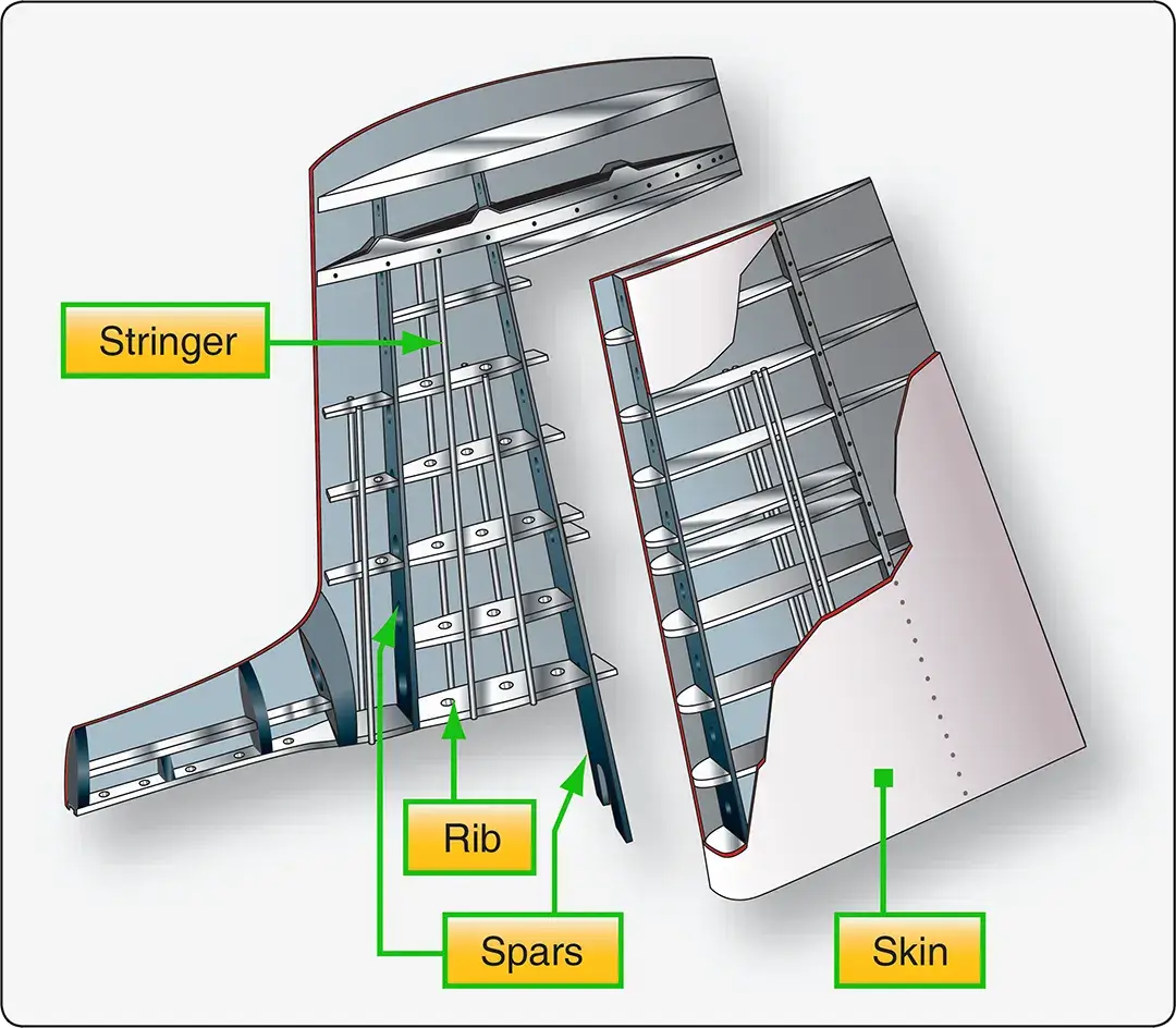 |
| Figure 3. Vertical stabilizer |
Empennage Configurations
Aircraft designers use several empennage configurations to achieve specific performance, stability, and operational requirements.
Conventional Tail
The conventional tail arrangement is the most common empennage design. It consists of a horizontal stabilizer mounted on the aft fuselage and a vertical stabilizer extending upward from the fuselage. Elevators and a rudder provide pitch and yaw control.
T-Tail Configuration
In a T-tail configuration, the horizontal stabilizer is mounted on top of the vertical stabilizer, forming a "T" shape. This arrangement places the horizontal stabilizer above the airflow disturbances generated by the wings and engines. T-tail designs are commonly used on both turbine-powered and some propeller-driven aircraft.
Stabilator
A stabilator, or all-moving horizontal tail, combines the functions of the horizontal stabilizer and elevator into a single movable surface. Instead of having a fixed stabilizer with a hinged elevator, the entire surface pivots to provide pitch control. Stabilators are commonly equipped with anti-servo tabs that increase control feel and can also be used for trim adjustments.
V-Tail Configuration
The V-tail uses two inclined tail surfaces instead of separate horizontal and vertical stabilizers. These surfaces perform the functions of both the elevator and rudder. The movable control surfaces, known as ruddervators, operate together to provide pitch control and differentially to provide yaw control.
Twin-Boom Configuration
Some aircraft use a twin-boom arrangement in which two tail booms extend aft from the wing or fuselage structure. In this configuration, the horizontal stabilizer spans between the booms while vertical stabilizers are mounted on the ends of the booms. This design provides adequate stability and control while accommodating specific engine or fuselage arrangements.
Dorsal Fin
Many aircraft incorporate a dorsal fin, which is an extension of the vertical stabilizer that extends forward along the upper fuselage. A dorsal fin increases directional stability and improves the effectiveness of the vertical stabilizer, particularly at higher angles of attack.
The rudder and elevator are primary flight control surfaces that are also part of the empennage. These movable surfaces are discussed in greater detail in the section on Primary Flight Control Surfaces.