Helicopter structures are designed to provide the unique flight characteristics that distinguish rotary-wing aircraft from fixed-wing aircraft. A simplified explanation of how a helicopter flies is that the rotors are rotating airfoils that provide lift similar to the way wings provide lift on a fixed-wing aircraft.
As the rotor blades rotate through the air, they generate aerodynamic lift in much the same way as a fixed-wing airfoil. By changing the angle of attack of the rotor blades, the amount of lift produced can be increased or decreased, causing the helicopter to climb or descend. Figure 1 shows the major components of a typical helicopter.
 |
| Figure 1. The major components of a helicopter are the airframe, fuselage, landing gear, powerplant/transmission, main rotor system, and antitorque system |
Airframe
The airframe, or fundamental structure, of a helicopter can be made of metal, composite materials, wood, or a combination of these materials. Typically, a composite component consists of many layers of fiber-impregnated resins, bonded to form a smooth panel. Tubular and sheet metal substructures are usually made of aluminum, though stainless steel or titanium are sometimes used in areas subject to higher stress or heat. Airframe design encompasses engineering, aerodynamics, materials technology, and manufacturing methods to achieve favorable balances of performance, reliability, and cost.
Fuselage
As with fixed-wing aircraft, helicopter fuselages and tail booms are often truss-type or semimonocoque structures of stress-skin design. Steel and aluminum tubing, formed aluminum, and aluminum skin are commonly used. Modern helicopter fuselage designs increasingly utilize advanced composite materials. Firewalls and engine decks are usually stainless steel.
Helicopter fuselages vary widely from those with a truss frame, two seats, no doors, and a monocoque shell flight compartment to those with fully enclosed airplane-style cabins as found on larger twin-engine helicopters. The multidirectional nature of helicopter flight makes wide-range visibility from the flight deck essential. Large, formed polycarbonate, glass, or plexiglass windscreens are common.
Landing Gear or Skids
As mentioned, a helicopter’s landing gear can be simply a set of tubular metal skids. Many helicopters do have landing gear with wheels, some retractable.
Powerplant and Transmission
The two most common types of engine used in helicopters are the reciprocating engine and the turbine engine. Reciprocating engines, also called piston engines, are generally used in smaller helicopters. Most training helicopters use reciprocating engines because they are relatively simple and inexpensive to operate.
Turbine Engines
Turbine engines are more powerful and are used in a wide variety of helicopters. They produce a tremendous amount of power for their size but are generally more expensive to operate. The turbine engine used in helicopters operates differently than those used in airplane applications.
In most applications, the exhaust outlets simply release expended gases and do not contribute to the forward motion of the helicopter. Because the airflow does not pass straight through the engine as it does in a turbojet engine and is not used for propulsion, the cooling effect of the air is limited. Approximately 75 percent of the incoming airflow is used to cool the engine.
The gas turbine engine mounted on most helicopters is made up of a compressor, combustion chamber, turbine, and accessory gearbox assembly. The compressor draws filtered air into the plenum chamber and compresses it. Common type filters are centrifugal swirl tubes where debris is ejected outward and blown overboard prior to entering the compressor, or engine barrier filters (EBF), a paper element type filter, encased in a frame with a screen/grill over the inlet, and usually coated with an oil. This design significantly reduces the ingestion of foreign object debris (FOD).
The compressed air is directed to the combustion section through discharge tubes where atomized fuel is injected into it. The air-fuel mixture is ignited and allowed to expand. This combustion gas is then forced through a series of turbine wheels causing them to turn. These turbine wheels provide power to both the engine compressor and the accessory gearbox. Depending on the model and manufacturer, operating speeds typically range from approximately 20,000 to over 50,000 rpm.
Power is provided to the main rotor and tail rotor systems through the freewheeling unit which is attached to the accessory gearbox power output gear shaft. The combustion gas is finally expelled through an exhaust outlet. The temperature of gas is measured at different locations and is referenced differently by each manufacturer. Some common terms are: inter-turbine temperature (ITT), exhaust gas temperature (EGT), or turbine outlet temperature (TOT). TOT is used throughout this discussion for simplicity purposes. [Figure 2]
 |
| Figure 2. Many helicopters use a turboshaft engine to drive the main transmission and rotor systems. The main difference between a turboshaft and a turbojet engine is that most of the energy produced by the expanding gases is used to drive a turbine rather than producing thrust through the expulsion of exhaust gases |
Transmission
The transmission system transfers power from the engine to the main rotor, tail rotor, and other accessories during normal flight conditions. The main components of the transmission system are the main rotor transmission, tail rotor drive system, clutch, and freewheeling unit. The freewheeling unit, or autorotative clutch, allows the main rotor transmission to drive the tail rotor drive shaft during autorotation.
Helicopter transmissions are normally lubricated and cooled with their own oil supply. A sight gauge is provided to check the oil level. Some transmissions have chip detectors located in the sump. These detectors are wired to warning lights located on the pilot’s instrument panel that illuminate in the event of an internal problem. Some chip detectors on modern helicopters have a “burn off” capability and attempt to correct the situation without pilot action. If the problem cannot be corrected on its own, the pilot must refer to the emergency procedures for that particular helicopter.
Main Rotor System
The rotor system is the rotating part of a helicopter which generates lift. The rotor consists of a mast, hub, and rotor blades. The mast is a cylindrical metal shaft that extends upwards from and is driven, and sometimes supported, by the transmission. At the top of the mast is the attachment point for the rotor blades called the hub. The rotor blades are then attached to the hub by any number of different methods. Main rotor systems are classified according to how the main rotor blades are attached and move relative to the main rotor hub. There are three basic classifications: rigid, semirigid, or fully articulated.
Rigid Rotor System
The simplest is the rigid rotor system. In this system, the rotor blades are rigidly attached to the main rotor hub and are not free to slide back and forth (drag) or move up and down (flap). [Figure 3]
 |
| Figure 3. Four-blade hingeless (rigid) main rotor. The hub is a single piece of forged rigid titanium |
The forces tending to make the rotor blades do so are absorbed by the flexible properties of the blade. The pitch of the blades, however, can be adjusted by rotation about the spanwise axis via the feathering hinges.
Semirigid Rotor System
The semirigid rotor system in Figure 4 makes use of a teetering hinge at the blade attach point. While preventing the blades from moving fore and aft, the teetering hinge does allow the blades to flap up and down. With this hinge, when one blade flaps up, the other flaps down.
 |
| Figure 4. The semirigid rotor system of the Robinson R22 |
Flapping is caused by a phenomenon known as dissymmetry of lift. As the plane of rotation of the rotor blades is tilted and the helicopter begins to move forward, an advancing blade and a retreating blade become established (on two-bladed systems). The relative windspeed is greater on an advancing blade than it is on a retreating blade. This causes greater lift to be developed on the advancing blade, causing it to rise up or flap. When blade rotation reaches the point where the blade becomes the retreating blade, the extra lift is lost and the blade flaps downward. [Figure 5]
 |
| Figure 5. The blade tip speed of this helicopter is approximately 300 knots. If the helicopter is moving forward at 100 knots, the relative windspeed on the advancing side is 400 knots. On the retreating side, it is only 200 knots. This difference in speed causes a dissymetry of lift |
Fully Articulated Rotor System
Fully articulated rotor blade systems provide hinges that allow the rotors to move fore and aft, as well as up and down. This lead-lag, drag, or hunting movement as it is called is in response to the Coriolis effect during rotational speed changes. When first starting to spin, the blades lag until centrifugal force is fully developed. Once rotating, a reduction in speed causes the blades to lead the main rotor hub until forces come into balance. Small variations in rotor blade speed and centrifugal forces cause the blades to “hunt.” They are free to do so in a fully articulating system due to being mounted on the vertical drag hinge.
One or more horizontal hinges provide for flapping on a fully articulated rotor system. Also, the feathering hinge allows blade pitch changes by permitting rotation about the spanwise axis. Various dampers and stops can be found on different designs to reduce shock and limit travel in certain directions. Figure 6 shows a fully articulated main rotor system with the features discussed.
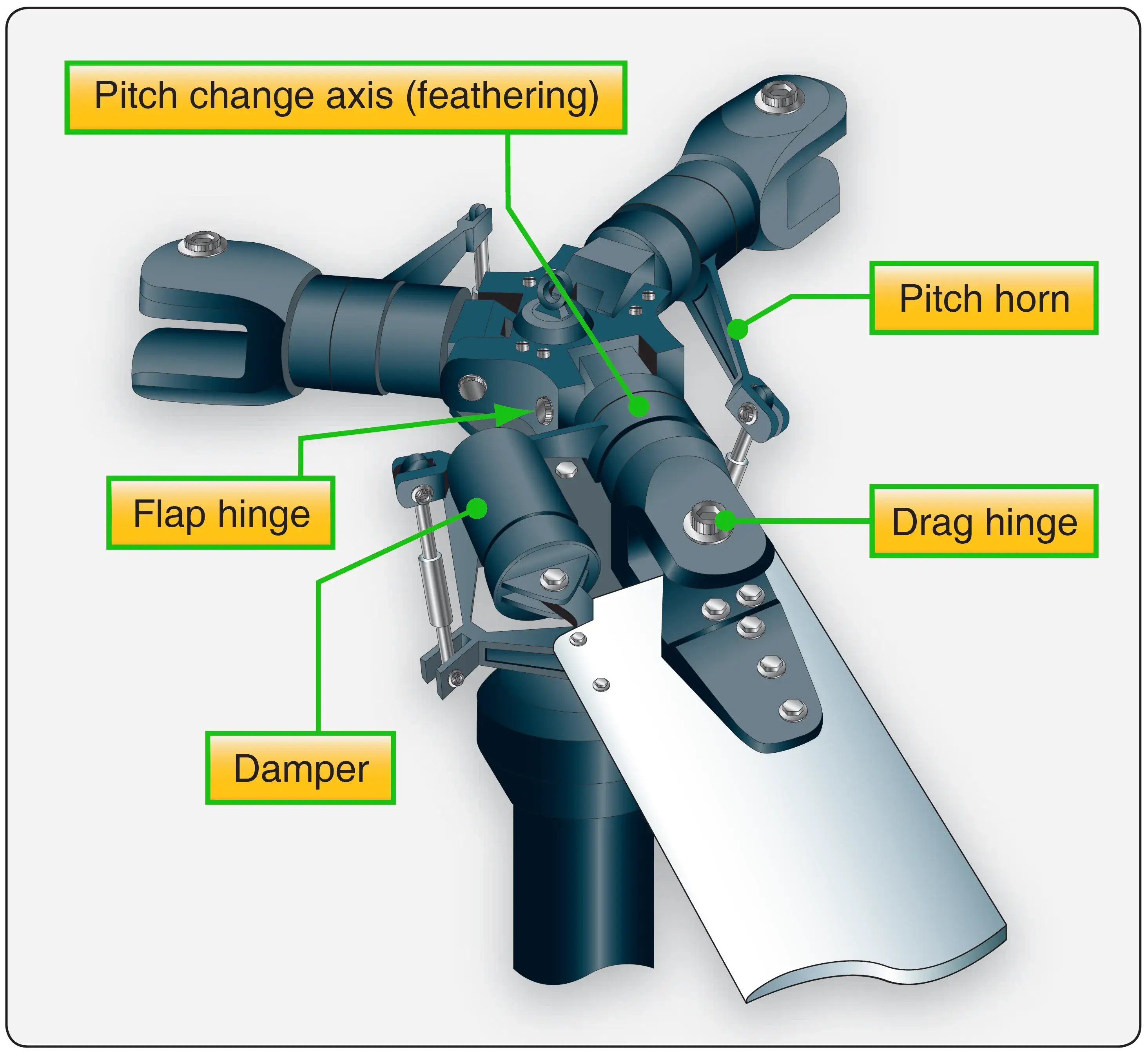 |
| Figure 6. Fully articulated rotor system |
Numerous designs and variations on the three types of main rotor systems exist. Engineers continually search for ways to reduce vibration and noise caused by the rotating parts of the helicopter. Toward that end, the use of elastomeric bearings in main rotor systems is increasing. These polymer bearings have the ability to deform and return to their original shape. As such, they can absorb vibration that would normally be transferred by steel bearings. They also do not require regular lubrication, which reduces maintenance.
Some modern helicopter main rotors have been designed with flexures. These are hubs and hub components that are made out of advanced composite materials. They are designed to take up the forces of blade hunting and dissymmetry of lift by flexing. As such, many hinges and bearings can be eliminated from the traditional main rotor system. The result is a simpler rotor mast with lower maintenance due to fewer moving parts. Often, designs using flexures incorporate elastomeric bearings. [Figure 7]
 |
| Figure 7. Five-blade articulated main rotor with elastomeric bearings |
Antitorque System
Most helicopters have between two and seven main rotor blades, although some modern designs use more. These rotors are usually made of a composite structure. The large rotating mass of a helicopter's main rotor blades produces torque. This torque increases with engine power and tries to spin the fuselage in the opposite direction. The tail boom and tail rotor, or antitorque rotor, counteract this torque effect. [Figure 8]
 |
| Figure 8. A tail rotor is designed to produce thrust in a direction opposite to that of the torque produced by the rotation of the main rotor blades. It is sometimes called an antitorque rotor |
Controlled with foot pedals, the countertorque of the tail rotor must be modulated as engine power levels are changed. This is done by changing the pitch of the tail rotor blades. This, in turn, changes the amount of countertorque, and the aircraft can be rotated about its vertical axis, allowing the pilot to control the direction the helicopter is facing.
Similar to the vertical stabilizer of a fixed-wing aircraft, a fin or pylon is also a common feature on rotorcraft. Normally, it supports the tail rotor assembly, although some tail rotors are mounted on the tail cone of the boom. Additionally, a horizontal member called a stabilizer is often constructed at the tail cone or on the pylon.
A Fenestron® is a unique tail rotor design which is actually a multiblade ducted fan mounted in the vertical pylon. It works the same way as an ordinary tail rotor, providing sideways thrust to counter the torque produced by the main rotors. [Figure 9]
 |
| Figure 9. A Fenestron or “fan-in-tail” antitorque system. This design provides an improved margin of safety during ground operations |
A NOTAR® antitorque system has no visible rotor mounted on the tail boom. Instead, an engine-driven adjustable fan is located inside the tail boom. NOTAR® is an acronym that stands for “no tail rotor.” As the speed of the main rotor changes, the speed of the NOTAR® fan changes. Air is vented out of two long slots on the right side of the tail boom, entraining main rotor wash to hug the right side of the tail boom, in turn creating a boundary-layer control effect that causes the airflow to adhere to the tail boom surface (Coandă effect), producing a lateral force that counteracts main rotor torque. This low pressure causes a force counter to the torque produced by the main rotor.
Additionally, the remainder of the air from the fan is sent through the tail boom to a vent on the aft left side of the boom where it is expelled. This action to the left causes an opposite reaction to the right, which is the direction needed to counter the main rotor torque. [Figures 10]
 |
| Figure 10. While in a hover, Coanda Effect supplies approximately two-thirds of the lift necessary to maintain directional control. The rest is created by directing the thrust from the controllable rotating nozzle |
Controls
The controls of a helicopter differ slightly from those found in an aircraft. The collective, operated by the pilot with the left hand, is pulled up or pushed down to increase or decrease the angle of attack on all of the rotor blades simultaneously. This increases or decreases lift and moves the aircraft up or down. On many helicopters, particularly those powered by reciprocating engines, the engine throttle control is located on the hand grip at the end of the collective. Many turbine helicopters use automatic engine control systems that reduce or eliminate the need for manual throttle adjustments during flight.
The cyclic control is located between the pilot's legs and can be moved in any direction to tilt the rotor disc. This causes the helicopter to move in the direction that the cyclic is moved. As stated, the foot pedals control the pitch of the tail rotor blades thereby balancing main rotor torque. Figures 11 and 12 illustrate the controls found in a typical helicopter.
 |
| Figure 11. The collective changes the pitch of all of the rotor blades simultaneously and by the same amount, thereby increasing or decreasing lift |
 |
| Figure 12. The cyclic changes the angle of the swash plate which changes the plane of rotation of the rotor blades. This moves the aircraft horizontally in any direction depending on the positioning of the cyclic |
Quick Review: Helicopter Structures and Systems
How do turbine engines in helicopters differ from those in conventional airplanes?
What are the three main classifications of main rotor systems?
- Rigid: Blades cannot flap (up/down) or drag (fore/aft); forces are absorbed through blade flexibility.
- Semirigid: Uses a teetering hinge allowing blades to flap symmetrically to counter dissymmetry of lift.
- Fully Articulated: Incorporates individual hinges or elastomeric bearings allowing blades to flap, feather, and lead-lag ("hunt") independently.