Main Rotor Transmission
The primary purpose of the main rotor transmission is to reduce engine output rpm to optimum rotor rpm. This reduction is different for the various helicopters. As an example, suppose the engine rpm of a specific helicopter is 2,700. A rotor speed of 450 rpm would require a 6:1 reduction. A 9:1 reduction would mean the rotor would turn at 300 rpm. Most helicopters use a dual-needle tachometer or a vertical scale instrument to show both engine and rotor rpm or a percentage of engine and rotor rpm. The rotor rpm indicator normally is used only during clutch engagement to monitor rotor acceleration, and in autorotation to maintain rpm within prescribed limits. [Figure 1] |
| Figure 1. There are various types of dual-needle tachometers; however, when the needles are superimposed, or married, the ratio of the engine rpm is the same as the gear reduction ratio |
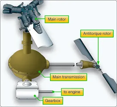
In helicopters with horizontally mounted engines, another purpose of the main rotor transmission is to change the axis of rotation from the horizontal axis of the engine to the vertical axis of the rotor shaft. [Figure 2]
 |
| Figure 2. The main rotor transmission and gearbox reduce engine output rpm to optimum rotor rpm and change the axis of rotation of the engine output shaft to the vertical axis for the rotor shaft |
Clutch
In a conventional airplane, the engine and propeller are permanently connected. However, in a helicopter there is a different relationship between the engine and the rotor. Because of the greater weight of a rotor in relation to the power of the engine, as compared to the weight of a propeller and the power in an airplane, the rotor must be disconnected from the engine when the starter is engaged. A clutch allows the engine to be started and then gradually pick up the load of the rotor.On free turbine engines, no clutch is required, as the gas producer turbine is essentially disconnected from the power turbine. When the engine is started, there is little resistance from the power turbine. This enables the gas producer turbine to accelerate to normal idle speed without the load of the transmission and rotor system dragging it down. As the gas pressure increases through the power turbine, the rotor blades begin to turn, slowly at first and then gradually accelerate to normal operating rpm.
On reciprocating helicopters, the two main types of clutches are the centrifugal clutch and the belt drive clutch.
Centrifugal Clutch
The centrifugal clutch is made up of an inner assembly and an outer drum. The inner assembly, which is connected to the engine driveshaft, consists of shoes lined with material similar to automotive brake linings. At low engine speeds, springs hold the shoes in, so there is no contact with the outer drum, which is attached to the transmission input shaft. As engine speed increases, centrifugal force causes the clutch shoes to move outward and begin sliding against the outer drum. The transmission input shaft begins to rotate, causing the rotor to turn, slowly at first, but increasing as the friction increases between the clutch shoes and transmission drum. As rotor speed increases, the rotor tachometer needle shows an increase by moving toward the engine tachometer needle. When the two needles are superimposed, the engine and the rotor are synchronized, indicating the clutch is fully engaged and there is no further slippage of the clutch shoes.Belt Drive Clutch
Some helicopters utilize a belt drive to transmit power from the engine to the transmission. A belt drive consists of a lower pulley attached to the engine, an upper pulley attached to the transmission input shaft, a belt or a series of V-belts, and some means of applying tension to the belts. The belts fit loosely over the upper and lower pulley when there is no tension on the belts. This allows the engine to be started without any load from the transmission. Once the engine is running, tension on the belts is gradually increased. When the rotor and engine tachometer needles are superimposed, the rotor and the engine are synchronized, and the clutch is then fully engaged. Advantages of this system include vibration isolation, simple maintenance, and the ability to start and warm up the engine without engaging the rotor.Freewheeling Unit
Since lift in a helicopter is provided by rotating airfoils, these airfoils must be free to rotate if the engine fails. The freewheeling unit automatically disengages the engine from the main rotor when engine rpm is less than main rotor rpm. This allows the main rotor and tail rotor to continue turning at normal in-flight speeds. The most common freewheeling unit assembly consists of a one-way sprag clutch located between the engine and main rotor transmission. This is usually in the upper pulley in a piston helicopter or mounted on the accessory gearbox in a turbine helicopter. When the engine is driving the rotor, inclined surfaces in the sprag clutch force rollers against an outer drum. This prevents the engine from exceeding transmission rpm. If the engine fails, the rollers move inward, allowing the outer drum to exceed the speed of the inner portion. The transmission can then exceed the speed of the engine. In this condition, engine speed is less than that of the drive system, and the helicopter is in an autorotative state.RELATED POSTS
- Aerodynamics, Assembly and Rigging
- Helicopter Flight Conditions
- Rotorcraft Controls
- Stabilizer Systems
- Helicopter Power Systems
- Airplane Assembly and Rigging
- Aircraft Rigging
- Aircraft Inspection
