Helicopter flight in forward motion introduces aerodynamic effects that do not exist in a hover. Dissymmetry of lift, blade flapping, cyclic feathering, and autorotation are fundamental rotor-system characteristics that allow helicopters to remain controllable throughout a wide range of flight conditions. Understanding these principles is essential for safe helicopter operation and performance.
Hovering Flight
During hovering flight, a helicopter maintains a constant position over a selected point, usually a few feet above the ground. For a helicopter to hover, the lift and thrust produced by the rotor system act straight up and must equal the weight and drag, which act straight down. [Figure 1]
 |
| Figure 1. To maintain a hover at a constant altitude, enough lift and thrust must be generated to equal the weight of the helicopter and the drag produced by the rotor blades |
While hovering, the amount of main rotor thrust can be changed to maintain the desired hovering altitude. This is done by changing the angle of incidence (by moving the collective) of the rotor blades and hence the AOA of the main rotor blades. Changing the AOA changes the drag on the rotor blades, and the power delivered by the engine must change as well to keep the rotor speed constant.
The weight that must be supported is the total weight of the helicopter and its occupants. If the amount of lift is greater than the actual weight, the helicopter accelerates upward until the lift force equals the weight and a new altitude is established; if lift is less than weight, the helicopter accelerates downward. When operating near the ground, the effect of the closeness to the ground changes this response.
The drag of a hovering helicopter is mainly induced drag incurred while the blades are producing lift. There is, however, some profile drag on the blades as they rotate through the air. Throughout the rest of this discussion, the term drag includes both induced and profile drag.
An important consequence of producing thrust is torque. Newton’s third law states that for every action there is an equal and opposite reaction. Therefore, as the engine turns the main rotor system in a counterclockwise direction, the helicopter fuselage tends to turn clockwise. The amount of torque is directly related to the amount of engine power being used to turn the main rotor system. Remember, as power changes, torque changes.
To counteract this torque-induced turning tendency, an antitorque rotor or tail rotor is incorporated into most helicopter designs. A pilot can vary the amount of thrust produced by the tail rotor in relation to the amount of torque produced by the engine. As the engine supplies more power to the main rotor, the tail rotor must produce more thrust to overcome the increased torque effect. This is done through the use of antitorque pedals.
Translating Tendency or Drift
During hovering flight, a single main rotor helicopter tends to drift or move in the direction of tail rotor thrust. This drifting tendency is called translating tendency. [Figure 2]
 |
| Figure 2. A tail rotor is designed to produce thrust in a direction opposite torque. The thrust produced by the tail rotor is sufficient to move the helicopter laterally |
To counteract this drift, one or more of the following features may be used. All examples are for a counterclockwise rotating main rotor system.
- The main transmission is mounted at a slight angle to the left (when viewed from behind) so that the rotor mast has a built-in tilt to oppose the tail rotor thrust.
- Flight controls can be rigged so that the rotor disc is tilted to the right slightly when the cyclic is centered. Whichever method is used, the tip-path plane is tilted slightly to the left in the hover.
- If the transmission is mounted so that the rotor shaft is vertical with respect to the fuselage, the helicopter “hangs” left skid low in the hover. The opposite is true for rotor systems turning clockwise when viewed from above.
- In forward flight, the tail rotor continues to push to the right, and the helicopter makes a small angle with the wind when the rotors are level and the slip ball is in the middle. This is called inherent sideslip.
Ground Effect
When hovering near the ground, a phenomenon known as ground effect takes place. This effect usually occurs at heights between the surface and approximately one rotor diameter above the surface. The friction of the ground causes the downwash from the rotor to move outwards from the helicopter. This changes the relative direction of the downwash from a purely vertical motion to a combination of vertical and horizontal motion. As the induced airflow through the rotor disc is reduced by the surface friction, the lift vector increases. This allows a lower rotor blade angle for the same amount of lift, which reduces induced drag.
Ground effect also restricts the generation of blade tip vortices due to the downward and outward airflow making a larger portion of the blade produce lift. When the helicopter gains altitude vertically, with no forward airspeed, induced airflow is no longer restricted, and the blade tip vortices increase with the decrease in outward airflow. As a result, drag increases, which requires a higher blade pitch angle and more power to move air downward through the rotor system.
Ground effect is at its maximum in a no-wind condition over a firm, smooth surface. Tall grass, rough terrain, and water surfaces alter the airflow pattern, causing an increase in rotor tip vortices. [Figure 3]
 |
| Figure 3. Air circulation patterns change when hovering out of ground effect (OGE) and when hovering in ground effect (IGE) |
Coriolis Effect (Law of Conservation of Angular Momentum)
The Coriolis effect is also referred to as the law of conservation of angular momentum. It states that the value of angular momentum of a rotating body does not change unless an external force is applied. In other words, a rotating body continues to rotate with the same rotational velocity until some external force is applied to change the speed of rotation.
Angular momentum is the product of moment of inertia (mass times the square of the distance from the center of rotation) and rotational velocity. Changes in angular velocity, known as angular acceleration and deceleration, take place as the mass of a rotating body is moved closer to or further away from the axis of rotation. The speed of the rotating mass increases or decreases in proportion to the square of the radius.
An excellent example of this principle is a spinning ice skater. The skater begins rotation on one foot, with the other leg and both arms extended. The rotation of the skater’s body is relatively slow. When a skater draws both arms and one leg inward, the moment of inertia (mass times radius squared) becomes much smaller and the body is rotating almost faster than the eye can follow. Because the angular momentum must remain constant (no external force applied), the angular velocity must increase.
The rotor blade rotating about the rotor hub possesses angular momentum. As the rotor begins to cone due to G-loading maneuvers, the diameter or the disc shrinks. Due to conservation of angular momentum, the blades continue to travel the same speed even though the blade tips have a shorter distance to travel due to reduced disc diameter. The action results in an increase in rotor rpm.
Most pilots arrest this increase with an increase in collective pitch. Conversely, as G-loading subsides and the rotor disc flattens out from the loss of G-load induced coning, the blade tips now have a longer distance to travel at the same tip speed. This action results in a reduction of rotor rpm.
However, if this drop in the rotor rpm continues to the point at which it attempts to decrease below normal operating rpm, the engine control system adds more fuel/ power to maintain the specified engine rpm. If the pilot does not reduce collective pitch as the disc unloads, the combination of engine compensation for the rpm slow down and the additional pitch as G-loading increases may result in exceeding the torque limitations or power the engines can produce.
Vertical Flight
Hovering is actually an element of vertical flight. Increasing the AOA of the rotor blades (pitch) while keeping their rotation speed constant generates additional lift and the helicopter ascends. Decreasing the pitch causes the helicopter to descend. In a no wind condition, when lift and thrust are less than weight and drag, the helicopter descends vertically. If lift and thrust are greater than weight and drag, the helicopter ascends vertically. [Figure 4]
 |
| Figure 4. To ascend vertically, more lift and thrust must be generated to overcome the forces of weight and drag |
Forward Flight
In steady forward flight with no change in airspeed or vertical speed, the four forces of lift, thrust, drag, and weight must be in balance. Once the tip-path plane is tilted forward, the total lift-thrust force is also tilted forward. This resultant lift-thrust force can be resolved into two components—lift acting vertically upward and thrust acting horizontally in the direction of flight. In addition to lift and thrust, there is weight (the downward acting force) and drag (the force opposing the motion of an airfoil through the air). [Figure 5]
 |
| Figure 5. The power required to maintain a straight-and-level flight and a stabilized airspeed |
In straight-and-level flight (constant heading and altitude), unaccelerated forward flight, lift equals weight and thrust equals drag. If lift exceeds weight, the helicopter accelerates vertically until the forces are in balance; if thrust is less than drag, the helicopter slows until the forces are in balance.
As the helicopter moves forward, it begins to lose altitude because lift is lost as thrust is diverted forward. However, as the helicopter begins to accelerate, the rotor system becomes more efficient due to the increased airflow. The result is excess power over that which is required to hover.
Continued acceleration causes an even larger increase in airflow through the rotor disc and more excess power. In order to maintain unaccelerated flight, the pilot must not make any changes in power or in cyclic movement. Any such changes would cause the helicopter to climb or descend. Once straight-and-level flight is obtained, the pilot should make note of the power (torque setting) required and not make major adjustments to the flight controls. [Figure 6]
 |
| Figure 6. Changing force vectors results in aircraft movement |
Translational Lift
Improved rotor efficiency resulting from directional flight is called translational lift. The efficiency of the hovering rotor system is greatly improved with each knot of incoming wind gained by horizontal movement of the aircraft or surface wind. As incoming wind produced by aircraft movement or surface wind enters the rotor system, turbulence and vortices are left behind and the flow of air becomes more horizontal.
In addition, the tail rotor becomes more aerodynamically efficient during the transition from hover to forward flight. Translational thrust occurs when the tail rotor becomes more aerodynamically efficient during the transition from hover to forward flight. As the tail rotor works in progressively less turbulent air, this improved efficiency produces more antitorque thrust, causing the nose of the aircraft to yaw left (with a main rotor turning counterclockwise) and forces the pilot to apply right pedal (decreasing the AOA in the tail rotor blades) in response.
In addition, during this period, the airflow affects the horizontal components of the stabilizer found on most helicopters which tends to bring the nose of the helicopter to a more level attitude. Figure 7 and Figure 8 show airflow patterns at different speeds and how airflow affects the efficiency of the tail rotor.
 |
| Figure 7. The airflow pattern for 1–5 knots of forward airspeed. Note how the downwind vortex is beginning to dissipate and induced flow down through the rear of the rotor system is more horizontal |
 |
| Figure 8. An airflow pattern at a speed of 10–15 knots. At this increased airspeed, the airflow continues to become more horizontal. The leading edge of the downwash pattern is being overrun and is well back under the nose of the helicopter |
Effective Translational Lift (ETL)
While transitioning to forward flight at about 16–24 knots, the helicopter experiences effective translational lift (ETL). As mentioned earlier in the discussion on translational lift, the rotor blades become more efficient as forward airspeed increases.
Between 16–24 knots, the rotor system completely outruns the recirculation of old vortices and begins to work in relatively undisturbed air. The flow of air through the rotor system is more horizontal, therefore induced flow and induced drag are reduced. The AOA is subsequently increased, which makes the rotor system operate more efficiently. This increased efficiency continues as airspeed increases until the best rate-of-climb airspeed is reached and total drag approaches its minimum value.
As speed increases, translational lift becomes more effective, the nose rises or pitches up, and the aircraft rolls to the right. The combined effects of dissymmetry of lift, gyroscopic precession, and transverse flow effect cause this tendency. It is important to understand these effects and anticipate correcting for them. Once the helicopter is transitioning through ETL, the pilot needs to apply forward and left lateral cyclic input to maintain a constant rotor-disc attitude. [Figure 9]
 |
| Figure 9. Effective translational lift is easily recognized in actual flight by a transient induced aerodynamic vibration and increased performance of the helicopter |
Dissymmetry of Lift
Dissymmetry of lift is the differential (unequal) lift between advancing and retreating halves of the rotor disc caused by the different wind flow velocity across each half. This difference in lift would cause the helicopter to be uncontrollable in any situation other than hovering in a calm wind. There must be a means of compensating, correcting, or eliminating this unequal lift to attain symmetry of lift.
When the helicopter moves through the air, the relative airflow through the main rotor disc is different on the advancing side than on the retreating side. The relative wind encountered by the advancing blade is increased by the forward speed of the helicopter, while the relative wind acting on the retreating blade is reduced by the helicopter's forward airspeed. Therefore, as a result of the relative windspeed, the advancing blade side of the rotor disc produces more lift than the retreating blade side. [Figure 10]
 |
| Figure 10. The blade tip speed of this helicopter is approximately 300 knots. If the helicopter is moving forward at 100 knots, the relative windspeed on the advancing side is 400 knots. On the retreating side, it is only 200 knots. This difference in speed causes a dissymmetry of lift |
If this condition was allowed to exist, a helicopter with a counterclockwise main rotor blade rotation would roll to the left because of the difference in lift. In reality, the main rotor blades flap and feather automatically to equalize lift across the rotor disc. Articulated rotor systems, usually with three or more blades, incorporate a horizontal hinge (flapping hinge) to allow the individual rotor blades to move, or flap up and down as they rotate. A semirigid rotor system (two blades) utilizes a teetering hinge, which allows the blades to flap as a unit. When one blade flaps up, the other blade flaps down.
As the rotor blade reaches the advancing side of the rotor disc, it reaches its maximum upward flapping velocity. [Figure 11A]
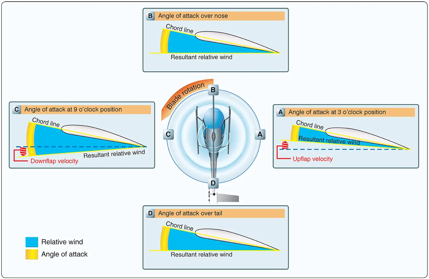 |
| Figure 11. The combined upward flapping (reduced lift) of the advancing blade and downward flapping (increased lift) of the retreating blade equalizes lift across the main rotor disk counteracting dissymmetry of lift |
When the blade flaps upward, the angle between the chord line and the resultant relative wind decreases. This decreases the AOA, which reduces the amount of lift produced by the blade. At position C, the rotor blade is at its maximum downward flapping velocity. Due to downward flapping, the angle between the chord line and the resultant relative wind increases. This increases the AOA and thus the amount of lift produced by the blade.
The combination of blade flapping and slow relative wind acting on the retreating blade normally limits the maximum forward speed of a helicopter. At a high forward speed, the retreating blade stalls due to high AOA and slow relative wind speed. This situation is called “retreating blade stall” and is evidenced by a nose-up pitch, vibration, and a rolling tendency—usually to the left in helicopters with counterclockwise blade rotation. Pilots can avoid retreating blade stall by not exceeding the never-exceed speed. This speed is designated VNE and is indicated on a placard and marked on the airspeed indicator by a red line.
During aerodynamic flapping of the rotor blades as they compensate for dissymmetry of lift, the advancing blade achieves maximum upward flapping displacement over the nose and maximum downward flapping displacement over the tail. This causes the tip-path plane to tilt to the rear and is referred to as blowback. Figure 12 shows how the rotor disc is originally oriented with the front down following the initial cyclic input.
 |
| Figure 12. To compensate for blowback, move the cyclic forward. Blowback is more pronounced with higher airspeeds |
As airspeed is gained and flapping eliminates dissymmetry of lift, the front of the disc comes up, and the back of the disc goes down. This reorientation of the rotor disc changes the direction in which total rotor thrust acts; the helicopter’s forward speed slows, but can be corrected with cyclic input. The pilot uses cyclic feathering to compensate for dissymmetry of lift, allowing control of the rotor disc attitude.
Cyclic feathering compensates for dissymmetry of lift (changes the AOA) in the following way. At a hover, equal lift is produced around the rotor system with equal pitch and AOA on all the blades and at all points in the rotor system (disregarding compensation for translating tendency). The rotor disc is parallel to the horizon.
To develop a thrust force, the rotor system must be tilted in the desired direction of movement. Cyclic feathering changes the angle of incidence differentially around the rotor system. Forward cyclic movements decrease the angle of incidence at one part of the rotor system while increasing the angle at another part. Maximum downward flapping of the blade over the nose and maximum upward flapping over the tail tilt both rotor disc and thrust vector forward.
To prevent blowback from occurring, the pilot must continually move the cyclic forward as the velocity of the helicopter increases. Figure 12 illustrates the changes in pitch angle as the cyclic is moved forward at increased airspeeds.
At a hover, the cyclic is centered and the pitch angle on the advancing and retreating blades is the same. At low forward speeds, moving the cyclic forward reduces pitch angle on the advancing blade and increases pitch angle on the retreating blade. This causes a slight rotor tilt. At higher forward speeds, the pilot must continue to move the cyclic forward. This further reduces pitch angle on the advancing blade and further increases pitch angle on the retreating blade. As a result, there is even more tilt to the rotor than at lower speeds.
This horizontal component of lift (thrust) increases helicopter airspeed. The higher airspeed induces blade flapping to maintain symmetry of lift. The combination of flapping and cyclic feathering maintains symmetry of lift and desired attitude on the rotor system and helicopter.
Autorotation
Autorotation is the state of flight in which the main rotor system of a helicopter is being turned by the action of air moving up through the rotor rather than engine power driving the rotor. [Figure 13]
 |
| Figure 13. During an autorotation, the upward flow of relative wind permits the main rotor blades to rotate at their normal speed. In effect, the blades are “gliding” in their rotational plane |
In normal, powered flight, air is drawn into the main rotor system from above and exhausted downward, but during autorotation, air moves up into the rotor system from below as the helicopter descends. Autorotation is permitted mechanically by a freewheeling unit, which is a special clutch mechanism that allows the main rotor to continue turning even if the engine is not running. If the engine fails, the freewheeling unit automatically disengages the engine from the main rotor, allowing the main rotor to rotate freely. It is the means by which a helicopter can be landed safely following an engine failure; consequently, all helicopters must demonstrate this capability to obtain certification.