Aircraft wheels are an important component of a landing gear system. With tires mounted upon them, they support the entire weight of the aircraft during taxi, takeoff, and landing. The typical aircraft wheel is lightweight, strong, and made from aluminum alloy. Some magnesium alloy wheels also exist. Early aircraft wheels were of single piece construction, much the same as the modern automobile wheel. As aircraft tires were improved for the purpose they serve, they were made stiffer to better absorb the forces of landing without blowing out or separating from the rim. Stretching such a tire over a single piece wheel rim was not possible. A two-piece wheel was developed. Early two-piece aircraft wheels were essentially one-piece wheels with a removable rim to allow mounting access for the tire. These are still found on older aircraft. [Figure 1]
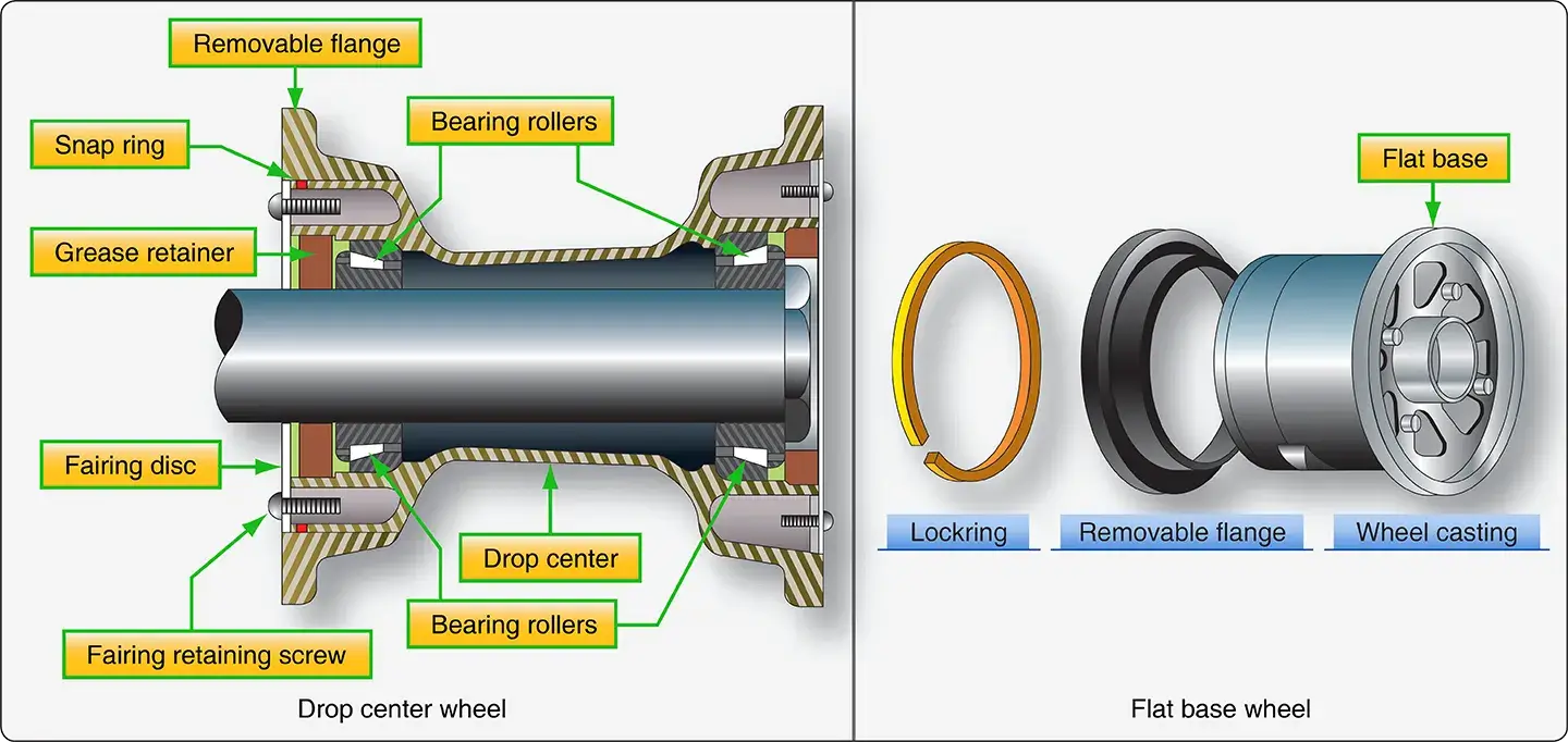 |
| Figure 1. Removable flange wheels found on older aircraft are either drop center or flat base types |
Later, wheels with two nearly symmetrical halves were developed. Nearly all modern aircraft wheels are of this two piece construction. [Figures 2 and 3]
 |
| Figure 2. Two-piece split-wheel aircraft wheels found on modern light aircraft |
 |
| Figure 3. Features of a two piece aircraft wheel found on a modern airliner |
Wheel Construction
The typical modern two-piece aircraft wheel is cast or forged from aluminum or magnesium alloy. The halves are bolted together and contain a groove at the mating surface for an o-ring, which seals the rim since most modern aircraft utilize tubeless tires. The bead seat area of a wheel is where the tire actually contacts the wheel. It is the critical area that accepts the significant tensile loads from the tire during landing. To strengthen this area during manufacturing, the bead seat area is typically rolled to prestress it with a compressive stress load.
Inboard Wheel Half
Wheel halves are not identical. The primary reason for this is that the inboard wheel half must have a means for accepting and driving the rotor(s) of the aircraft brakes that are mounted on both main wheels. Tangs on the rotor are fitted into steel reinforced keyways on many wheels. Other wheels have steel keys bolted to the inner wheel halves. These are made to fit slots in the perimeter of the brake rotor. Some small aircraft wheels have provisions for bolting the brake rotor to the inner wheel half. Regardless, the inner wheel half is distinguishable from the outer wheel half by its brake mounting feature. [Figure 4]
 |
| Figure 4. Keys on the inner wheel half of an aircraft wheel used to engage and rotate the rotors of a disc brake |
Both wheel halves contain a bearing cavity formed into the center that accepts the polished steel bearing cup, tapered roller bearing, and grease retainer of a typical wheel bearing set-up. A groove may also be machined to accept a retaining clip to hold the bearing assembly in place when the wheel assembly is removed. The wheel bearings are a very important part of the wheel assembly.
The inner wheel half of a wheel used on a high performance aircraft is likely to have one or more thermal plugs. [Figure 5] During heavy braking, temperatures can become so great that tire temperature and pressure rise to a level resulting in explosion of the wheel and tire assembly. The thermal plug core is filled with a low melting point alloy. Before tire and wheel temperatures reach the point of explosion, the core melts and deflates the tire. The tire must be removed from service, and the wheel must be inspected in accordance with the wheel manufacturer’s instructions before return to service if a thermal plug melts. Adjacent wheel assemblies should also be inspected for signs of damage. A heat shield is commonly installed under the inserts designed to engage the brake rotor to assist in protecting the wheel and tire assembly from overheating.
 |
| Figure 5. Heavy use of the aircraft brakes can cause tire air temperature and pressure to rise to a level resulting in explosion of the wheel assembly. To alleviate this, thermal plug(s) mounted in the inner wheel half of a high performance aircraft wheels are made with a fusible core that melts and releases the air from the tire before explosion |
An overinflation safety plug may also be installed in the inner wheel half. This is designed to rupture and release all of the air in the tire should it be over inflated. The fill valve is also often installed in the inner wheel half with the stem extending through holes in the outer wheel half to permit access for inflation and deflation.
Outboard Wheel Half
The outboard wheel half bolts to the inboard wheel half to make up the wheel assembly upon which the tire is mounted. The center boss is constructed to receive a bearing cup and bearing assembly as it does on the inboard wheel half. The outer bearing and end of the axle is capped to prevent contaminants from entering this area. Aircraft with anti-skid brake systems typically mount the wheel-spin transducer here. It is sealed and may also serve as a hub cap. The 737 outer wheel half illustrated in Figure 3 also has a hub cap fairing over the entire wheel half. This is to fair it with the wind since the outer wheel half does not close behind a gear door on this aircraft. Hub caps may also be found on fixed gear aircraft.
The outboard wheel half provides a convenient location of the valve stem used to inflate and deflate tubeless tires. Alternately, it may contain a hole through which a valve stem extension may pass from the inner wheel half or the valve stem itself may fit through such a hole if a tube-type tire is used.
Wheel Inspection
An aircraft wheel assembly is inspected while on the aircraft as often as possible. A more detailed inspection and any testing or repairs may be accomplished with the wheel assembly removed from the aircraft.
On Aircraft Inspection
The general condition of the aircraft wheel assemblies can be inspected while on the aircraft. Any signs of suspected damage that may require removal of the wheel assembly from the aircraft should be investigated.
Proper Installation
The landing gear area is such a hostile environment that the technician should inspect the landing gear including the wheels, tires, and brakes whenever possible. Proper installation of the wheels should not be taken for granted. All wheel tie bolts and nuts must be in place and secure. A missing bolt is grounds for removal, and a thorough inspection of the wheel halves in accordance with the wheel manufacturer’s procedures must be performed due to the stresses that may have occurred. The wheel hub dust cap and anti-skid sensor should also be secure. The inboard wheel half should interface with the brake rotor with no signs of chafing or excessive movement. All brake keys on the wheel must be present and secure.
Examine the wheels for cracks, flaked paint, and any evidence of overheating. Inspect thermal plugs to ensure no sign of the fusible alloy having been melted. Thermal plugs that have permitted pressure loss in the tire require that the wheel assembly be removed for inspection. All other wheels with brakes and thermal plugs should be inspected closely while on the aircraft to determine if they too have overheated. Each wheel should be observed overall to ensure it is not abnormally tilted. Flanges should not be missing any pieces, and there should be no areas on the wheel that show significant impact damage.
Axle Nut Torque
Axle nut torque is of extreme importance on an aircraft wheel installation. If the nut is too loose, the bearing and wheel assembly may have excessive movement. The bearing cup(s) could loosen and spin, which could damage the wheel. There could also be impact damage from the bearing rollers which leads to bearing failure. [Figure 6] An over-torqued axle nut prevents the bearing from properly accepting the weight load of the aircraft. The bearing spins without sufficient lubrication to absorb the heat caused by the higher friction level. This too leads to bearing failure. All aircraft axle nuts must be installed and torqued in accordance with the airframe manufacturer’s maintenance procedures.
 |
| Figure 6. Improper loose torque on the axle nut can cause excessive end play leading to bearing race damage known as scalloping. Eventually, this leads to bearing failure |
Off Aircraft Wheel Inspection
Discrepancies found while inspecting a wheel mounted on the aircraft may require further inspection with the wheel removed from the aircraft. Other items such as bearing condition, can only be performed with the wheel assembly removed. A complete inspection of the wheel requires that the tire be removed from the wheel rim. Observe the following caution when removing a wheel assembly from an aircraft.
Loosening the Tire from the Wheel Rim
After inflation and usage, an aircraft tire has a tendency to adhere to the wheel, and the bead must be broken to remove the tire. There are mechanical and hydraulic presses designed for this purpose. In the absence of a device specifically made for the job, an arbor press can be used with patience working sequentially around the wheel as close as possible to the bead. [Figure 7] As stated above, there should be no air pressure in the tire while it is being pressed off of the wheel. Never pry a tire off of the rim with a screwdriver or other device. The wheels are relatively soft. Any nick or deformation causes a stress concentration that can easily lead to wheel failure.
 |
| Figure 7. Tire beads must be broken from the wheel to remove the tire. A mechanical removal tool designed for breaking the bead is shown in (A); a hydraulic press designed with the capacity for large aircraft wheels is shown in (B); and an arbor press is shown in (C). All are tools available to the technician for this purpose |
Disassembly of the Wheel
Disassembly of the wheel should take place in a clean area on a flat surface, such as a table. Remove the wheel bearing first and set aside for cleaning and inspecting. The tie bolts can then be removed. Do not use an impact tool to disassemble the tie bolts. Aircraft wheels are made of relatively soft aluminum and magnesium alloys. They are not designed to receive the repeated hammering of an impact tool and will be damaged if used.
Cleaning the Wheel Assembly
Clean the wheel halves with the solvent recommended by the wheel manufacturer. Use of a soft brush helps this process. Avoid abrasive techniques, materials, and tools, such as scrapers, capable of removing the finish off of the wheel. Corrosion can quickly form and weaken the wheel if the finish is missing in an area. When the wheels are clean, they can be dried with compressed air.
Cleaning the Wheel Bearings
The bearings should be removed from the wheel to be cleaned with the recommended solvent, such as varsol, naptha, or Stoddard® solvent. Soaking the bearings in solvent is acceptable to loosen any dried-on grease. Bearings are brushed clean with a soft bristle brush and dried with compressed air. Never rotate the bearing while drying with compressed air. The high speed metal to metal contact of the bearing rollers with the race causes heat that damages the metal surfaces. The bearing parts could also cause injury should the bearing come apart. Always avoid steam cleaning of bearings. The surface finish of the metals will be compromised leading to early failure.
Wheel Bearing Inspection
Once cleaned, the wheel bearing is inspected. There are many unacceptable conditions of the bearing and bearing cup, which are grounds for rejection. In fact, nearly any flaw detected in a bearing assembly is likely to be grounds for replacement.
Common conditions of a bearing that are cause for rejection are as follows:
Galling - caused by rubbing of mating surfaces. The metal gets so hot it welds, and the surface metal is destroyed as the motion continues and pulls the metal apart in the direction of motion. [Figure 8]
 |
| Figure 8. Galling is caused by rubbing of mating surfaces. The metal gets so hot it welds, and the surface metal is destroyed as the motion continues and pulls the metal apart in the direction of motion |
Spalling - a chipped away portion of the hardened surface of a bearing roller or race. [Figure 9]
 |
| Figure 9. Spalling is a chipped away portion of the hardened surface of a bearing roller or race |
Overheating - caused by lack of sufficient lubrication results in a bluish tint to the metal surface. The ends of the rollers shown were overheated causing the metal to flow and deform, as well as discolor. The bearing cup raceway is usually discolored as well. [Figure 10]
 |
| Figure 10. Overheating caused by lack of sufficient lubrication results in a bluish tint to the metal surface. The ends of the rollers shown were overheated causing the metal to flow and deform, as well as discolor. The bearing cup raceway is usually discolored as well |
Brinelling - caused by excessive impact. It appears as indentations in the bearing cup raceways. Any static overload or severe impact can cause true brinelling that leads to vibration and premature bearing failure. [Figure 11]
 |
| Figure 11. Brinelling is caused by excessive impact. It appears as indentations in the bearing cup raceways. Any static overload or severe impact can cause true brinelling, which leads to vibration and premature bearing failure |
False Brinelling - caused by vibration of the bearing while in a static state. Even with a static overload, lubricant can be forced from between the rollers and the raceway. Submicroscopic particles removed at the points of metal-tometal contact oxidize. They work to remove more particles spreading the damage. This is also known as frictional corrosion. It can be identified by a rusty coloring of the lubricant. [Figure 12]
 |
| Figure 12. False brinelling is caused by vibration of the bearing while in a static state. Even with a static overload, it can force the lubricant from between the rollers and the raceway. Submicroscopic particles removed at the points of metal-to-metal contact oxidize. They work to remove more particles spreading the damage. This is also known as frictional corrosion. It can be identified by a rusty coloring of the lubricant |
Staining and surface marks - located on the bearing cup as grayish black streaks with the same spacing as the rollers and caused by water that has gotten into the bearing. It is the first stage of deeper corrosion that follows. [Figure 13]
 |
| Figure 13. Staining and surface marks on the bearing cup that are grayish black streaks with the same spacing as the rollers are caused by water that has gotten into the bearing. It is the first stage of deeper corrosion that will follow |
Etching and corrosion - caused when water and the damage caused by water penetrates the surface treatment of the bearing element. It appears as a reddish/brown discoloration. [Figure 14]
 |
| Figure 14. Etching and corrosion is caused when water, and the damage caused by water, penetrates the surface treatment of the bearing element. It appears as a reddish/brown discoloration |
Bruising - caused by fine particle contamination possibly from a bad seal or improper maintenance of bearing cleanliness. It leaves a less than smooth surface on the bearing cup. [Figure 15]
 |
| Figure 15. Bruising is caused by fine particle contamination possibly from a bad seal or improper maintenance of bearing cleanliness. It leaves a less than smooth surface on the bearing cup |
The bearing cup does not require removal for inspection; however, it must be firmly seated in the wheel half boss. There should be no evidence that a cup is loose or able to spin. [Figure 16] The cup is usually removed by heating the wheel in a controlled oven and pressing it out or tapping it out with a non-metallic drift. The installation procedure is similar. The wheel is heated and the cup is cooled with dry ice before it is tapped into place with a non-metallic hammer or drift. The outside of the race is often sprayed with primer before insertion. Consult the wheel manufacturer’s maintenance manual for specific instructions.
 |
| Figure 16. Bearing cups should be tight in the wheel boss and should never rotate. The outside of a bearing cup that was spinning while installed in the wheel is shown |
Bearing Handling and Lubrication
Handling of bearings is of the utmost importance. Contamination, moisture, and vibration, even while the bearing is in a static state, can ruin a bearing. Avoid conditions where these may affect bearings and be sure to install and torque bearings into place according to the manufacturer’s instructions.
Proper lubrication is a partial deterrent to negative environmental impacts on a bearing. Use the lubricant recommended by the manufacturer. Use of a pressure bearing packing tool or adapter is also recommended as the best method to remove any contaminants from inside the bearing that may have remained after cleaning. [Figure 17]
 |
| Figure 17. A pressure bearing lubricating tool |
Inspection of the Wheel Halves
A thorough visual inspection of each wheel half should be conducted for discrepancies specified in the wheel manufacturer’s maintenance data. Use of a magnifying glass is recommended. Corrosion is one of the most common problems encountered while inspecting wheels. Locations where moisture is trapped should be checked closely. It is possible to dress out some corrosion according to the manufacturer’s instructions. An approved protective surface treatment and finish must be applied before returning the wheel to service. Corrosion beyond stated limits is cause for rejection of the wheel.
In addition to corrosion, cracks in certain areas of the wheel are particularly prevalent. One such area is the bead seat area. [Figure 18] The high stress of landing is transferred to the wheel by the tire in this contact area. Hard landings produce distortion or cracks that are very difficult to detect. This is a concern on all wheels and is most problematic in highpressure, forged wheels. Dye penetrant inspection is generally ineffective when checking for cracks in the bead area. There is a tendency for cracks to close up tightly once the tire is dismounted, and the stress is removed from the metal. Eddy current inspection of the bead seat area is required. Follow the wheel manufacturer’s instruction when performing the eddy current check.
 |
| Figure 18. The bead seat areas of a light aircraft wheel set. Eddy current testing for cracks in the bead seat area is common |
The wheel brake disc drive key area is another area in which cracks are common. The forces experienced when the keys drive the disc against the stopping force of the brakes are high. Generally, a dye penetrant test is sufficient to reveal cracks in this area. All drive keys should be secure with no movement possible. No corrosion is permitted in this area. [Figure 19]
 |
| Figure 19. Inspection for cracks in the wheel disc drive key area is performed with dye penetrant on many wheels |
Wheel Tie Bolt Inspection
Wheel half tie bolts are under great stress while in service and require inspection. The tie bolts stretch and change dimension usually at the threads and under the bolt head. These are areas where cracks are most common. Magnetic particle inspection can reveal these cracks. Follow the maintenance manual procedures for inspecting tie bolts.
Key and Key Screw Inspection
On most aircraft inner wheel halves, keys are screwed or bolted to the wheel to drive the brake disc(s). The drive keys are subject to extreme forces when the brakes are applied. As mentioned, there should be no movement between the wheel and the keys. The bolts should be checked for security, and the area around the keys should be inspected for cracks. There is also a limitation on how worn the keys can be since too much wear allows excessive movement. The wheel manufacturer’s maintenance instructions should be used to perform a complete inspection of this critical area.
Fusible Plug Inspection
Fusible plugs or thermal plugs must be inspected visually. These threaded plugs have a core that melts at a lower temperature than the outer part of the plug. This is to release air from the tire should the temperature rise to a dangerous level. A close inspection should reveal whether any core has experienced deformation that might be due to high temperature. If detected, all thermal plugs in the wheel should be replaced with new plugs. [Figure 20]
 |
| Figure 20. Visually inspect the core of a thermal or fusible plug for deformation associated with heat exposure. Replace all of the plugs if any appear to have begun to deform |
Balance Weights
The balance of an aircraft wheel assembly is important. When manufactured, each wheel set is statically balanced. Weights are added to accomplish this if needed. They are a permanent part of the wheel assembly and must be installed to use the wheel. The balance weights are bolted to the wheel halves and can be removed when cleaning and inspecting the wheel. They must be re-fastened in their original position. When a tire is mounted to a wheel, balancing of the wheel and tire assembly may require that additional weights be added. These are usually installed around the circumference of the outside of the wheel and should not be taken as substitutes for the factory wheel set balance weights. [Figure 21]
 |
| Figure 21. Two piece aircraft wheels are statically balanced when manufactured and may include weights attached to each wheel half that must stay with the wheel during its entire serviceable life |