Aircraft tires may be tube-type or tubeless. They support the weight of the aircraft while it is on the ground and provide the necessary traction for braking and stopping. The tires also help absorb the shock of landing and cushion the roughness of takeoff, rollout, and taxi operations. Aircraft tires must be carefully maintained to perform as required. They accept a variety of static and dynamic stresses and must do so dependably in a wide range of operating conditions.
Tire Classification
Aircraft tires are classified in various ways including by: type, ply rating, whether they are tube-type or tubeless, and whether they are bias ply tires or radials. Identifying a tire by its dimensions is also used. Each of these classifications is discussed as follows.
Types
A common classification of aircraft tires is by type as classified by the United States Tire and Rim Association. While there are nine types of tires only Types I, III, VII, and VIII are still in production. Type VIII tires are also known as three-part nomenclature tires.
Type I tires are manufactured, but their design is no longer active. They are used on fixed gear aircraft and are designated only by their nominal overall diameter in inches. These are smooth profile tires that are obsolete for use in the modern aviation fleet. They may be found on older aircraft.
Type III tires are common general aviation tires. They are typically used on light aircraft with landing speeds of 160 miles per hour (mph) or less. Type III tires are relatively low-pressure tires that have small rim diameters when compared to the overall width of the tire. They are designed to cushion and provide flotation from a relatively large footprint. Type III tires are designated with a two number system. The first number is the nominal section width of the tire, and the second number is the diameter of the rim the tire is designed to mount upon. [Figure 1]
 |
| Figure 1. Type III aircraft tires are identified via a two-number system with a (-) separating the numbers. The first number is the tire section width in inches. The second number is the rim diameter in inches. For example: 6.00 – 6 is a Cessna 172 tire that is 6.00 inches wide and fits on a rim that has a diameter of 6 inches |
Type VII tires are high-performance tires found on jet aircraft. They are inflated to high-pressure and have exceptional high load carrying capability. The section width of Type VII tires is typically narrower than Type III tires. Identification of Type VII aircraft tires involves a two-number system. An X is used between the two numbers. The first number designates the nominal overall diameter of the tire. The second number designates the section width. [Figure 2]
 |
| Figure 2. A Type VII aircraft tire is identified by its two number designation. The first number represents the tire’s overall diameter in inches and the second number represents the section width in inches. Type VII designators separate the first and second number an “X.” For example: 26 X 6.6 dentifies a tire that is 26 inches in diameter with a 6.6-inch nominal width |
Type VIII aircraft tires are also known as three-part nomenclature tires. [Figure 3] They are inflated to very high pressure and are used on high-performance jet aircraft. The typical Type VIII tire has relatively low profile and is capable of operating at very high speeds and very high loads. It is the most modern design of all tire types. The three-part nomenclature is a combination of Type III and Type VII nomenclature where the overall tire diameter, section width, and rim diameter are used to identify the tire. The X and “–” symbols are used in the same respective positions in the designator.
 |
| Figure 3. A Type VIII or three-part nomenclature tire is identified by 3 parameters: overall diameter, section width, and rim diameter. They are arranged in that order with the first two separated by an “X” and the second two separated by a “–.” For example: 18 X 4.25—10 designates a tire that is 18 inches in diameter with a 4.25-inch section width to be mounted on a 10- inch wheel rim |
When three-part nomenclature is used on a Type VIII tire, dimensions may be represented in inches or in millimeters. Bias tires follow the designation nomenclature and radial tires replace the “–” with the letter R. For example, 30 X 8.8 R 15 designates a Type VIII radial aircraft tire with a 30-inch tire diameter, an 8.8-inch section width to be mounted on a 15-inch wheel rim.
A few special designators may also be found for aircraft tires. When a B appears before the identifier, the tire has a wheel rim to section width ratio of 60 to 70 percent with a bead taper of 15 degrees. When an H appears before the identifier, the tire has a 60 to 70 percent wheel rim to section width ratio but a bead taper of only 5 degrees.
Ply Rating
Tire plies are reinforcing layers of fabric encased in rubber that are laid into the tire to provide strength. In early tires, the number of plies used was directly related to the load the tire could carry. Nowadays, refinements to tire construction techniques and the use of modern materials to build up aircraft tires makes the exact number of plies somewhat irrelevant when determining the strength of a tire. However, a ply rating is used to convey the relative strength of an aircraft tire. A tire with a high ply rating is a tire with high strength able to carry heavy loads regardless of the actual number of plies used in its construction.
Tube-Type or Tubeless
As stated, aircraft tires can be tube-type or tubeless. This is often used as a means of tire classification. Tires that are made to be used without a tube inserted inside have an inner liner specifically designed to hold air. Tube-type tires do not contain this inner liner since the tube holds the air from leaking out of the tire. Tires that are meant to be used without a tube have the word tubeless on the sidewall. If this designation is absent, the tire requires a tube. Consult the aircraft manufacturer’s maintenance information for any allowable tire damage and the use of a tube in a tubeless tire.
Bias Ply or Radial
Another means of classifying an aircraft tire is by the direction of the plies used in construction of the tire, either bias or radial. Traditional aircraft tires are bias ply tires. The plies are wrapped to form the tire and give it strength. The angle of the plies in relation to the direction of rotation of the tire varies between 30° and 60°. In this manner, the plies have the bias of the fabric from which they are constructed facing the direction of rotation and across the tire. Hence, they are called bias tires. The result is flexibility as the sidewall can flex with the fabric plies laid on the bias. [Figure 4]
 |
| Figure 4. A bias ply tire has the fabric bias oriented with and across the direction of rotation and the sidewall. Since fabric can stretch on the bias, the tire is flexible, and can absorb loads. Strength is obtained by adding plies |
Some modern aircraft tires are radial tires. The plies in radial tires are laid at a 90° angle to the direction of rotation of the tire. This configuration puts the non-stretchable fiber of the plies perpendicular to the sidewall and direction of rotation. This creates strength in the tire allowing it to carry high loads with less deformation. [Figure 5]
 |
| Figure 5. A radial tire has the fiber strands of the ply fabric oriented with and at 90° to the direction of rotation and the tire sidewall. This restricts flexibility directionally and the flexibility of the sidewall while it strengthens the tire to carry heavy loads |
Tire Construction
An aircraft tire is constructed for the purpose it serves. Unlike an automobile or truck tire, it does not have to carry a load for a long period of continuous operation. However, an aircraft tire must absorb the high impact loads of landing and be able to operate at high speeds even if only for a short time. The deflection built into an aircraft tire is more than twice that of an automobile tire. This enables it to handle the forces during landings without being damaged. Only tires designed for an aircraft as specified by the manufacturer should be used.
It is useful to the understanding of tire construction to identify the various components of a tire and the functions contributed to the overall characteristics of a tire. Refer to Figure 6 for tire nomenclature used in this discussion.
 |
| Figure 6. Construction nomenclature of an aircraft tire |
Bead
The tire bead is an important part of an aircraft tire. It anchors the tire carcass and provides a dimensioned, firm mounting surface for the tire on the wheel rim. Tire beads are strong. They are typically made from high-strength carbon steel wire bundles encased in rubber. One, two, or three bead bundles may be found on each side of the tire depending on its size and the load it is designed to handle. Radial tires have a single bead bundle on each side of the tire. The bead transfers the impact loads and deflection forces to the wheel rim. The bead toe is closest to the tire centerline and the bead heel fits against the flange of the wheel rim.
An apex strip is additional rubber formed around the bead to give a contour for anchoring the ply turn-ups. Layers of fabric and rubber called flippers are placed around the beads to insulate the carcass from the beads and improve tire durability. Chafers are also used in this area. Chafer strips made of fabric or rubber are laid over the outer carcass plies after the plies are wrapped around the beads. The chafers protect the carcass from damage during mounting and demounting of the tire. They also help reduce the effects of wear and chafing between the wheel rim and the tire bead especially during dynamic operations.
Carcass Plies
Carcass plies, or casing plies as they are sometimes called, are used to form the tire. Each ply consists of fabric, usually nylon, sandwiched between two layers of rubber. The plies are applied in layers to give the tire strength and form the carcass body of the tire. The ends of each ply are anchored by wrapping them around the bead on both sides of the tire to form the ply turn-ups. As mentioned, the angle of the fiber in the ply is manipulated to create a bias tire or radial tire as desired. Typically, radial tires require fewer plies than bias tires.
Once the plies are in place, bias tires and radial tires each have their own type of protective layers on top of the plies but under the tread of the running surface of the tire. On bias tires, these single or multiple layers of nylon and rubber are called tread reinforcing plies. On radial tires, an undertread and a protector ply do the same job. These additional plies stabilize and strengthen the crown area of the tire. They reduce tread distortion under load and increase stability of the tire at high speeds. The reinforcing plies and protector plies also help resist puncture and cutting while protecting the carcass body of the tire.
Tread
The tread is the crown area of the tire designed to come in contact with the ground. It is a rubber compound formulated to resist wear, abrasion, cutting, and cracking. It also is made to resist heat build-up. Most modern aircraft tire tread is formed with circumferential grooves that create tire ribs. The grooves provide cooling and help channel water from under the tire in wet conditions to increase adhesion to the ground surface. Tires designed for aircraft frequently operated from unpaved surfaces may have some type of cross-tread pattern. Older aircraft without brakes or brakes designed only to aid in taxi may not have any grooves in the tread. An all-weather tread may be found on some aircraft tires. This tread has typical circumferential ribs in the center of the tire with a diamond patterned cross tread at the edge of the tire. [Figure 7]
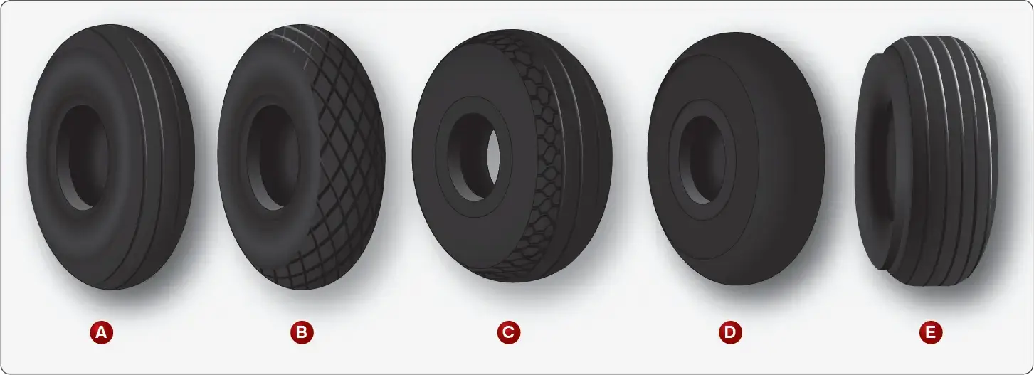 |
| Figure 7. Aircraft tire treads are designed for different uses. A is a rib tread designed for use on paved surfaces. It is the most common aircraft tire tread design. B is a diamond tread designed for unpaved runways. C is an all weather tread that combines a ribbed center tread with a diamond tread pattern of the edges. D is a smooth tread tire found on older, slow aircraft without brakes designed for stopping. E is a chine tire used on the nose gear of aircraft with fuselage mounted jet engines to deflect runway water away from the engine intake(s) |
The tread is designed to stabilize the aircraft on the operating surface and wears with use. Many aircraft tires are designed with protective undertread layers as described above. Extra tread reinforcement is sometimes accomplished with breakers. These are layers of nylon cord fabric under the tread that strengthen the tread while protecting the carcass plies. Tires with reinforced tread are often designed to be re-treaded and used again once the tread has worn beyond limits. Consult the tire manufacturer’s data for acceptable tread wear and re-tread capability for a particular tire.
Sidewall
The sidewall of an aircraft tire is a layer of rubber designed to protect the carcass plies. It may contain compounds designed to resist the negative effects of ozone on the tire. It also is the area where information about the tire is contained. The tire sidewall imparts little strength to the cord body. Its main function is protection.
The inner sidewall of a tire is covered by the tire inner liner. A tube-type tire has a thin rubber liner adhered to the inner surface to prevent the tube from chafing on the carcass plies. Tubeless tires are lined with a thicker, less permeable rubber. This replaces the tube and contains the nitrogen or inflation air within the tire and keeps from seeping through the carcass plies.
The inner liner does not contain 100 percent of the inflation gas. Small amounts of nitrogen or air seep through the liner into the carcass plies. This seepage is released through vent holes in the lower outer sidewall of the tires. These are typically marked with a green or white dot of paint and must be kept unobstructed. Gas trapped in the plies could expand with temperature changes and cause separation of the plies, thus weakening the tire leading to tire failure. Tube-type tires also have seepage holes in the sidewall to allow air trapped between the tube and the tire to escape. [Figure 8]
 |
| Figure 8. A sidewall vent marked by a colored dot must be kept free from obstruction to allow trapped air or nitrogen to escape from the carcass plies of the tire |
Chine
Some tire sidewalls are mounded to form a chine. A chine is a special built-in deflector used on nose wheels of certain aircraft, usually those with fuselage mounted engines. The chine diverts runway water to the side and away from the intake of the engines. [Figure 7-E] Tires with a chine on both sidewalls are produced for aircraft with a single nose wheel.
Tire Inspection on the Aircraft
Tire condition is inspected while mounted on the aircraft on a regular basis. Inflation pressure, tread wear and condition, and sidewall condition are continuously monitored to ensure proper tire performance.
Inflation
To perform as designed, an aircraft tire must be properly inflated. The aircraft manufacturer’s maintenance data must be used to ascertain the correct inflation pressure for a tire on a particular aircraft. Do not inflate to a pressure displayed on the sidewall of the tire or by how the tire looks. Tire pressure is checked while under load and is measured with the weight of the aircraft on the wheels. Loaded versus unloaded pressure readings can vary as much as 4 percent. Tire pressure measured with the aircraft on jacks or when the tire is not installed is lower due to the larger volume of the inflation gas space inside of the tire. On a tire designed to be inflated to 160 psi, this can result in a 6.4 psi error. A calibrated pressure gauge should always be used to measure inflation pressure. Digital and dial-type pressure gauges are more consistently accurate and preferred. [Figure 9]
 |
| Figure 9. A calibrated bourdon tube dial-type pressure gauge or a digital pressure gauge is recommended for checking tire pressure |
Aircraft tires disperse the energy from landing, rollout, taxi, and takeoff in the form of heat. As the tire flexes, heat builds and is transferred to the atmosphere, as well as to the wheel rim through the tire bead. Heat from braking also heats the tire externally. A limited amount of heat is able to be handled by any tire beyond which structural damage occurs.
An improperly inflated aircraft tire can sustain internal damage that is not readily visible and that can lead to tire failure. Tire failure upon landing is always dangerous. An aircraft tire is designed to flex and absorb the shock of landing. Temperature rises as a result. However, an underinflated tire may flex beyond design limits of the tire. This causes excessive heat build-up that weakens the carcass construction. To ensure tire temperature is maintained within limits, tire pressure must be checked and maintained within the proper range on a daily basis or before each flight if the aircraft is only flown periodically. Important reasons for maintaining proper tire pressure are to prolong tire life and prevent tire damage.
Tire pressure should be measured at ambient temperature. Fluctuations of ambient temperature greatly affect tire pressure and complicate maintenance of pressure within the allowable range for safe operation. Tire pressure typically changes 1 percent for every 5 °F of temperature change. When aircraft are flown from one environment to another, ambient temperature differences can be vast. Maintenance personnel must ensure that tire pressure is adjusted accordingly. For example, an aircraft with the correct tire pressure departing Phoenix, Arizona where the ambient temperature is 100 °F arrives in Vail, Colorado where the temperature is 50 °F. The 50° difference in ambient temperature results in a 10 percent reduction in tire pressure. Therefore, the aircraft could land with underinflated tires that may be damaged due to over-temperature from flexing beyond design limits as described above. An increase in tire pressure before takeoff in Phoenix, Arizona prevents this problem as long as the tires are not inflated beyond the allowable limit provided in the maintenance data.
When checking tire pressure, allow 3 hours to elapse after a typical landing to ensure the tire has cooled to ambient temperature. The correct tire pressure for each ambient temperature is typically provided by the manufacturer on a table or graph.
In addition to overheating, underinflated aircraft tires wear unevenly, which leads to premature tire replacement. They may also creep or slip on the wheel rim when under stress or when the brakes are applied. Severely underinflated tires can pinch the sidewall between the rim and the runway causing sidewall and rim damage. Damage to the bead and lower sidewall area are also likely. This type of abuse like any over flexing damages the integrity of the tire and it must be replaced. In dual-wheel setups, a severely underinflated tire affects both tires and both should be replaced.
Overinflation of aircraft tires is another undesirable condition. While carcass damage due to overheating does not result, adherence to the landing surface is reduced. Over a long period of time, overinflation leads to premature tread wear. Therefore, overinflation reduces the number of cycles in service before the tire must be replaced. It makes the tire more susceptible to bruises, cutting, shock damage, and blowout. [Figure 10]
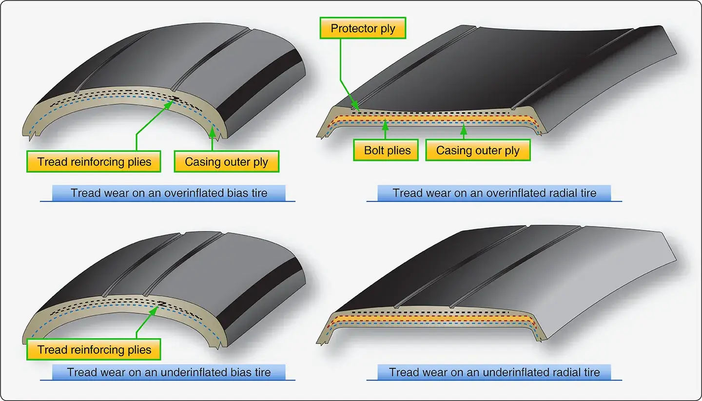 |
| Figure 10. Tires that are overinflated lack adherence to the runway and develop excess tread wear in the center of the tread. Tires that are underinflated develop excess tread wear on the tire shoulders. Overheating resulting in internal carcass damage and potential failure are possible from flexing the tire beyond design limits |
Tread Condition
Condition of an aircraft tire tread is able to be determined while the tire is inflated and mounted on the aircraft. The following is a discussion of some of the tread conditions and damage that the technician may encounter while inspecting tires.
Tread Depth and Wear Pattern
Evenly worn tread is a sign of proper tire maintenance. Uneven tread wear has a cause that should be investigated and corrected. Follow all manufacturer instructions specific to the aircraft when determining the extent and serviceability of a worn tire. In the absence of this information, remove any tire that has been worn to the bottom of a tread groove along more than 1/8 of the circumference of the tire. If either the protector ply on a radial tire or the reinforcing ply on a bias tire is exposed for more than 1ś8 of the tire circumference, the tire should also be removed. A properly maintained evenly worn tire usually reaches its wear limits at the centerline of the tire. [Figure 11]
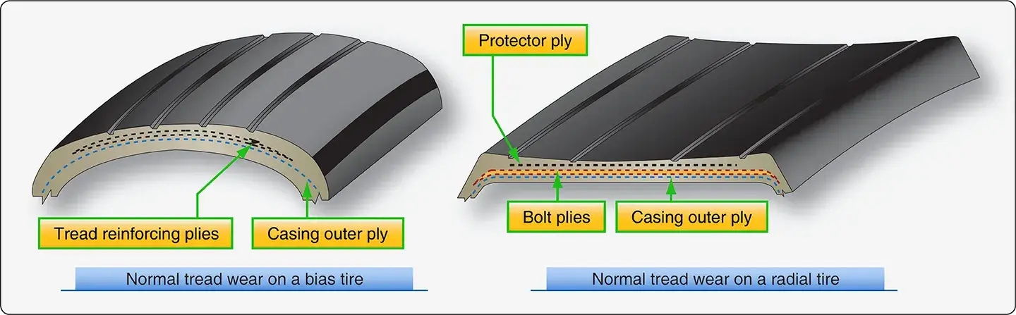 |
| Figure 11. Normal tire wear |
Asymmetrical tread wear may be caused by the wheels being out of alignment. Follow the manufacturer’s instructions while checking caster, camber, tow-in, and tow-out to correct this situation. Occasionally, asymmetrical tire wear is a result of landing gear geometry that cannot, or is not, required to be corrected. It may also be caused by regular taxiing on a single engine or high speed cornering while taxiing. It is acceptable to remove the tire from the wheel rim, turn it around, and remount it to even up tread wear if the tire passes all other criteria of inspection for serviceability.
Removal of a tire before it is worn beyond limits to be eligible for retreading is cost effective and good maintenance practice. Considerable traction is lost when tire tread is severely worn and must also be considered when inspecting a tire for condition. [Figure 12] Consult airframe manufacturer and tire manufacturer specifications for wear and retread limitations.
 |
| Figure 12. Tread wear on a bias ply tire (left) and a radial tire (right) show wear beyond limits of serviceability but still eligible to be retreaded |
Tread Damage
In addition to tread wear, an aircraft tire should be inspected for damage. Cuts, bruises, bulges, embedded foreign objects, chipping, and other damage must be within limits to continue the tire in service. Some acceptable methods of dealing with this type of damage are described below. All damage, suspected damage, and areas with leaks should be marked with chalk, a wax marker, paint stick, or other device before the tire is deflated or removed. Often, it is impossible to relocate these areas once the tire is deflated. Tires removed for retread should be marked in damaged areas to enable closer inspection of the extent of the damage before the new tread is installed. [Figure 13]
 |
| Figure 13. Marking of damaged area to enable closer inspection |
Foreign objects embedded in a tire’s tread are of concern and should be removed when not embedded beyond the tread. Objects of questionable depth should only be removed after the tire has been deflated. A blunt awl or appropriately sized screwdriver can be used to pry the object from the tread. Care must be exercised to not enlarge the damaged area with the removal tool. [Figure 14] Once removed, assess the remaining damage to determine if the tire is serviceable. A round hole caused by a foreign object is acceptable only if it is 3/8-inch or less in diameter. Embedded objects that penetrate or expose the casing cord body of a bias ply tire or the tread belt layer of a radial tire cause the tire to become unairworthy and it must be removed from service.
 |
| Figure 14. Deflate a tire before removing or probing any area where a foreign object is lodged |
Cuts and tread undercutting can also render a tire unairworthy. A cut that extends across a tread rib is cause for tire removal. These can sometimes lead to a section of the rib to peel away from the tire. [Figure 15] Consult the aircraft maintenance manual, airline operations manual, or other technical documents applicable to the aircraft tire in question.
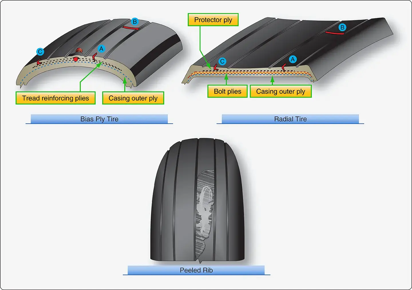 |
| Figure 15. Remove an aircraft tire from service when the depth of a cut exposes the casing outer plies of a bias ply tire or the outer belt layer of a radial tire (A); a tread rib has been severed across the entire width (B); or, when undercutting occurs at the base of any cut (C). These conditions may lead to a peeled rib |
A flat spot on a tire is the result of the tire skidding on the runway surface while not rotating. This typically occurs when the brakes lock on while the aircraft is moving. If the flat spot damage does not expose the reinforcing ply of a bias tire or the protector ply of a radial tire, it may remain in service. However, if the flat spot causes vibration, the tire must be removed. Landing with a brake applied can often cause a severe flat spot that exposes the tire under tread. It can also cause a blowout. The tire must be replaced in either case. [Figure 16]
 |
| Figure 16. Landing with the brake on causes a tire flat spot that exposes the under tread and requires replacement of the tire |
A bulge or separation of the tread from the tire carcass is cause for immediate removal and replacement of the tire. Mark the area before deflation as it could easily become undetectable without air in the tire. [Figure 17]
 |
| Figure 17. Bulges and tread separation are cause for removal of a tire from service |
Operation on a grooved runway can cause an aircraft tire tread to develop shallow chevron shaped cuts. These cuts are allowed for continued service, unless chunks or cuts into the fabric of the tire result. Deep chevrons that cause a chunk of the tread to be removed should not expose more than 1 square inch of the reinforcing or protector ply. Consult the applicable inspection parameters to determine the allowable extent of chevron cutting. [Figure 18]
 |
| Figure 18. Chevron cuts in a tire are caused by operation on grooved runway surfaces. Shallow chevron cuts are permitted on aircraft tires |
Tread chipping and chunking sometimes occurs at the edge of the tread rib. Small amounts of rubber lost in this way are permissible. Exposure of more than 1 square inch of the reinforcing or protector ply is cause for removal of the tire. [Figure 19]
 |
| Figure 19. Tread chipping and chunking of a tire requires that the tire be removed from service if more than 1 square inch of the reinforcing ply or protector ply is exposed |
Cracking in a tread groove of an aircraft tire is generally not acceptable if more than ¼-inch of the reinforcing or protector ply is exposed. Groove cracks can lead to undercutting of the tread, which eventually can cause the entire tread to be thrown from the tire. [Figure 20]
 |
| Figure 20. A thrown tread can result from a groove crack or tread undercutting and must be removed from service |
Oil, hydraulic fluid, solvents, and other hydrocarbon substances contaminate tire rubber, soften it, and make it spongy. A contaminated tire must be removed from service. If any volatile fluids come in contact with the tire, it is best to wash the tire or area of the tire with denatured alcohol followed by soap and water. Protect tires from contact with potentially harmful fluids by covering tires during maintenance in the landing gear area.
Tires are also subject to degradation from ozone and weather. Tires on aircraft parked outside for long periods of time can be covered for protection from the elements. [Figure 21]
 |
| Figure 21. Cover tires to protect from harmful chemicals and from the elements when parked outside for long periods of time |
Sidewall Condition
The primary function of the sidewall of an aircraft tire is protection of the tire carcass. If the sidewall cords are exposed due to a cut, gouge, snag, or other injury, the tire must be replaced. Mark the area of concern before removal of the tire. Damage to the sidewall that does not reach the cords is typically acceptable for service. Circumferential cracks or slits in the sidewall are unacceptable. A bulge in a tire sidewall indicates possible delamination of the sidewall carcass plies. The tire must immediately be removed from service.
Weather and ozone can cause cracking and checking of the sidewall. If this extends to the sidewall cords, the tire must be removed from service. Otherwise, sidewall checking as shown in Figure 22 does not affect the performance of the tire and it may remain in service.
 |
| Figure 22. Cracking and checking in the sidewall of a tire is acceptable for service as long as it does not extend to or expose the sidewall carcass plies |
Tire Removal
Removal of any tire and wheel assembly should be accomplished following all aircraft manufacturer’s instructions for the procedure. Safety procedures are designed for the protection of the technician and the maintenance of aircraft parts in serviceable condition. Follow all safety procedures to prevent personal injury and damage to aircraft parts and assemblies.
An aircraft tire and wheel assembly, especially a high pressure assembly that has been damaged or overheated, should be treated as though it may explode. Never approach such a tire while its temperature is still elevated above ambient temperature. Once cooled, approach a damaged tire and wheel assembly from an oblique angle advancing toward the shoulder of the tire. [Figure 23]
 |
| Figure 23. To avoid potential injury, approach a tire/wheel assembly that has damage or has been overheated at an angle toward the tire shoulder only after it has cooled to ambient temperature |
Deflate all unserviceable and damaged tires before removal from the aircraft. Use a valve core/deflation tool to deflate the tire. Stand to the side—away from the projectile path of the valve core. A dislodged valve core propelled by internal tire pressure can cause serious human injury. When completely deflated, remove the valve core. [Figure 24] A tire and wheel assembly in airworthy condition may be removed to access other components for maintenance without deflating the tire. This is common practice, such as when accessing the brake when the wheel assembly is immediately reinstalled.
For tracking purposes, ensure damaged areas of a tire are marked before deflation. Record all known information about an unserviceable tire and attach it to the tire for use by the retread repair station.
 |
| Figure 24. The tire valve core should be removed after the tire is completely deflated and before the tire and wheel assembly is removed from the aircraft |
Once removed from the aircraft, a tire must be separated from the wheel rim on which it is mounted. Proper equipment and technique should be followed to avoid damage to the tire and wheel. The wheel manufacturer’s maintenance information is the primary source for dismounting guidelines.
The bead area of the tire sits firmly against the rim shoulder and must be broken free. Always use proper bead breaking equipment for this purpose. Never pry a tire from a wheel rim as damage to the wheel is inevitable. The wheel tie bolts must remain installed and fully tightened when the bead is broken from the rim to prevent damage to the wheel half mating surfaces.
When the bead breaking press contact surface is applied to the tire, it should be as close to the wheel as possible without touching it during the entire application of pressure. Tires and rims of different sizes require contact pads suitable for the tire. Hand presses and hydraulic presses are available. Apply the pressure and hold it to allow the bead to move on the rim. Gradually progress around the rim until the tire bead is broken free. Ring-type bead breakers apply pressure around the circumference of the entire sidewall so rotation is not required. [Figure 25] Once the bead is broken free, the wheel halves may be disassembled. [Figure 26]
Radial tires have only one bead bundle on each side of the tire. The sidewall is more flexible in this area than a bias ply tire. The proper tooling should be used, and pressure should be applied slowly to avoid heavy distortion of the sidewall. Lubrication may be applied and allowed to soak into the tire-wheel interface. Only soapy tire solutions should be used. Never apply a hydrocarbon based lubricant to an aircraft tire as this contaminates the rubber compound used to construct the tire. Beads on tube-type and tubeless tires are broken free in a similar manner.
 |
| Figure 25. A ring adapter applies pressure around the entire circumference of the lower sidewall of the tire to break the bead free from the wheel rim. The diameter of the adapter must be correct for the tire and the travel limited so as to not injure the tire |
 |
| Figure 26. An electrohydraulic tire bead breaker (left) used on large tires and a manual tire bead breaker (right) used on small tires |
Tire Inspection Off of the Aircraft
Once a tire has been removed from the wheel rim, it should be inspected for condition. It may be possible to retread the tire at an approved repair station and return it to service. A sequential inspection procedure helps ensure no parts of the tire are overlooked. Mark and record the extent of all damage. Tires must only be repaired by those with the experience and equipment to do so. Most tire repairs are accomplished at a certified tire repair facility.
When inspecting a tire removed from the aircraft, pay special attention to the bead area since it must provide an airtight seal to the wheel rim and transfer forces from the tire to the rim. Inspect the bead area closely as it is where the heat is concentrated during tire operation. Surface damage to the chafer is acceptable and can be repaired when the tire is retreaded. Other damage in the bead area is usually cause for rejection. Damage to the turn-ups, ply separation at the bead, or a kinked bead are examples of bead area damage that warrant the tire be discarded. The bead area of the tire may sustain damage or have an altered appearance or texture on a tire that has been overheated. Consult a certified tire repair station or retread facility when in doubt about the condition observed. The wheel rim must also be inspected for damage. An effective seal without slippage, especially on tubeless tires, is dependent on the condition and integrity of the wheel in the bead seat area.
Overheating of a tire weakens it even though the damage might not be obvious. Any time a tire is involved in an aborted takeoff, severe braking, or the thermal plug in the wheel has melted to deflate the tire before explosion, the tire must be removed. On a dual installation, both tires must be removed. Even if only one tire shows obvious damage or deflates, the loads experienced by the mate are excessive. Internal damage such as ply separation, is likely. The history of having experienced an overheat event is all that is required for the tire to be discarded.
Damaged or suspected damaged areas of the tire should be re-inspected while the tire is off the aircraft. Cuts can be probed to check for depth and extent of damage below the tread. In general, damage that does not exceed 40 percent of the tire plies can be repaired when the tire is retreaded. Small punctures with a diameter on the tire inner surface of less than 1/8-inch and a diameter on the outer surface of less than 1/4-inch can also be repaired and retreaded. A bulge caused by ply separation is reason to discard a tire. However, a bulge caused by tread separation from the tire carcass may be repairable during retread. Exposed sidewall cord or sidewall cord damage is unacceptable and the tire cannot be repaired or retreaded. Consult the tire manufacturer or certified retreader for clarification on damage to a tire.
Tire Repair and Retreading
The technician should follow airframe and tire manufacturer instructions to determine if a tire is repairable. Many example guidelines have also been given in this section. Nearly all tire repairs must be made at a certified tire repair facility equipped to perform the approved repair. Bead damage, ply separation, and sidewall cord exposure all require that the tire be scrapped. Inner liner condition on tubeless tires is also critical. Replacing the tube in a tube-type tire is performed by the technician as are mounting and balancing all types of aircraft tires.
Aircraft tires are very expensive. They are also extremely durable. The effective cost of a tire over its life can be reduced by having the tread replaced while the carcass is still sound and injuries are within repairable limits. The technician inspects a tire to pre-qualify it for retread so that the cost of shipping it to the retread repair facility is not incurred if there is no chance to retread the tire. The tire retreader inspects and tests every tire to a level beyond the capability of the hangar or line technician. Shearography, an optical nondestructive testing method that provides detailed information about the internal integrity of the tire, is used by tire retread repair facilities to ensure a tire carcass is suitable for continued service.
Tires that are retreaded are marked as such. They are not compromised in strength and give the performance of a new tire. No limits are established for the number of times a tire can be retreaded. This is based on the structural integrity of the tire carcass. A well maintained main gear tire may be able to be retreaded a handful of times before fatigue renders the carcass unairworthy. Some nose tires can be retreaded nearly a dozen times.
Tire Storage
An aircraft tire can be damaged if stored improperly. A tire should always be stored vertically so that it is resting on its treaded surface. Horizontal stacking of tires is not recommended. Storage of tires on a tire rack with a minimum 3–4-inch flat resting surface for the tread is ideal and avoids tire distortion.
If horizontal stacking of tires is necessary, it should only be done for a short time. The weight of the upper tires on the lower tires cause distortion, possibly making it difficult for the bead to seat when mounting tubeless tires. A bulging tread also stresses rib grooves and opens the rubber to ozone attack in this area. [Figure 27] Never stack aircraft tires horizontally for more than 6 months. Stack no higher than four tires if the tire is less than 40-inches in diameter and no higher than three tires if greater than 40-inches in diameter. The environment in which an aircraft tire is stored is critical. The ideal location in which to store an aircraft tire is cool, dry, and dark, free from strong air currents and dirt.
 |
| Figure 27. Ozone cracking in a tire tread groove is facilitated by horizontal stacking |
An aircraft tire contains natural rubber compounds that are prone to degradation from chemicals and sunlight. Ozone (O3) and oxygen (O2) cause degradation of tire compounds. Tires should be stored away from strong air currents that continually present a supply of one or both of these gases. Fluorescent lights, mercury vapor lights, electric motors, battery chargers, electric welding equipment, electric generators, and similar shop equipment produce ozone and should not be operated near aircraft tires. Mounted inflated tires can be stored with up to 25 percent less pressure than operating pressure to reduce vulnerability from ozone attacks. Sodium vapor lighting is acceptable. Storage of an aircraft tire in the dark is preferred to minimize degradation from ultraviolet (UV) light. If this is not possible, wrap the tire in dark polyethylene or paper to form an ozone barrier and to minimize exposure to UV light.
Common hydrocarbon chemicals, such as fuels, oils, and solvents, should not contact a tire. Avoid rolling tires through spills on the hangar or shop floor and be sure to clean any tire immediately if contaminated. Dry the tire and store all tires in a dry place away from any moisture, which has a deteriorating effect on the rubber compounds. Moisture with foreign elements may further damage the rubber and fabric of a tire. Dirty areas must be avoided.
Tires are made to operate in a wide range of temperatures. However, storage should be at cool temperatures to minimize degradation. A general range for safe aircraft tire storage is between 32 °F and 104 °F. Temperatures below this are acceptable but higher temperatures must be avoided.
Aircraft Tubes
Many aircraft tires accept a tube inside to contain the inflation air. Tube-type tires are handled and stored in similar fashion as tubeless tires. A number of issues concerning the tubes themselves must be addressed.
Tube Construction and Selection
Aircraft tire tubes are made of a natural rubber compound. They contain the inflation air with minimal leakage. Unreinforced and special reinforced heavy duty tubes are available. The heavy duty tubes have nylon reinforcing fabric layered into the rubber to provide strength to resist chafing and to protect against heat such as during braking.
Tubes come in a wide range of sizes. Only the tube specified for the applicable tire size must be used. Tubes that are too small stress the tube construction.
Tube Storage and Inspection
An aircraft tire tube should be kept in the original carton until put into service to avoid deterioration through exposure to environmental elements. If the original carton is not available, the tube can be wrapped in several layers of paper to protect it. Alternately, for short time periods only, a tube may be stored in the correct size tire it is made for while inflated just enough to round out the tube. Application of talc to the inside of the tire and outside of the tube prevents sticking. Remove the tube and inspect it and the tire before permanently mounting the assembly. Regardless of storage method, always store aircraft tubes in a cool, dry, dark place away from ozone producing equipment and moving air.
When handling and storing aircraft tire tubes, creases are to be avoided. These weaken the rubber and eventually cause tube failure. Creases and wrinkles also tend to be chafe points for the tube when mounted inside the tire. Never hang a tube over a nail or peg for storage.
An aircraft tube must be inspected for leaks and damage that may eventually cause a leak or failure. To check for leaks, remove the tube from the tire. Inflate the tube just enough to have it take shape but not stretch. Immerse a small tube in a container of water and look for the source of air bubbles. A large tube may require that water be applied over the tube. Again look for the source of bubbles. The valve core should also be wetted to inspect it for leaks.
There is no mandatory age limit for an aircraft tire tube. It should be elastic without cracks or creases in order to be considered serviceable. The valve area is prone to damage and should be inspected thoroughly. Bend the valve to ensure there are no cracks at the base where it is bonded to the tire or in the area where it passes through the hole in the wheel rim. Inspect the valve core to ensure it is tight and that it does not leak.
If an area of a tube experiences chafing to the point where the rubber is thinned, the tube should be discarded. The inside diameter of the tube should be inspected to ensure it has not been worn by contact with the toe of the tire bead. Tubes that have taken an unnatural set should be discarded. [Figure 28]
 |
| Figure 28. During inspection, an aircraft tire tube should retain its natural contour. Tubes with thinned areas or that have taken a set should be discarded and replaced |
Tire Inspection
It is important to inspect the inside of a tube-type tire before installing a tube for service. Any protrusions or rough areas should be cause for concern, as these tend to abrade the tube and may cause early failure. Follow the tire, tube, and aircraft manufacturer’s inspection criterion when inspecting aircraft tires and tubes.
Tire Mounting
A licensed technician is often called upon to mount an aircraft tire onto the wheel rim in preparation for service. In the case of a tube-type tire, the tube must also be mounted. The following section presents general procedures for these operations using tube-type and tubeless tires. Be sure to have the proper equipment and training to perform the work according to manufacturer’s instructions.
Tubeless Tires
Aircraft tire and wheel assemblies are subject to enormous stress while in service. Proper mounting ensures tires perform to the limits of their design. Consult and follow all manufacturer’s service information including bolt torques, lubrication and balancing requirements, and inflation procedures.
As mentioned, a wheel assembly that is to have a tire mounted upon it must be thoroughly inspected to ensure it is serviceable. Pay close attention to the bead seat area, which should be smooth and free from defects. The wheel half mating surface should be in good condition. The O-ring should be lubricated and in good condition to ensure it seals the wheel for the entire life of the tire. [Figure 29]
 |
| Figure 29. The wheel half O-ring for a tubeless tire wheel assembly must be in good condition and lubricated to seal for the entire life of the tire. The mating surfaces of the wheel halves must also be in good condition |
A final inspection of the tire to be mounted should be made. Most important is to check that the tire is specified for the aircraft application. It should say tubeless on the sidewall. The part number, size, ply rating, speed rating, and technical standard order (TSO) number should also be on the sidewall and be approved for the aircraft installation. Visually check the tire for damage from shipping and handling. There should be no permanent deformation of the tire. It should pass all inspections for cuts and other damage discussed in the previous sections of this chapter. Clean the tire bead area with a clean shop towel and soap and water or denatured alcohol. Inspect the inside of the tire for condition. There should be no debris inside the tire.
Tire beads are sometimes lubricated when mounted on aluminum wheels. Follow the manufacturer’s instructions and use only the non-hydrocarbon lubricant specified. Never lubricate any tire bead with grease. Do not use lubricants with magnesium alloy wheels. Most radial tires are mounted without lubricant. The airframe manufacturer may specify lubrication for a radial tire in a few cases.
When the wheel halves and tires are ready to be mounted, careful attention must be given to tire orientation and the balance marks on the wheel halves and tire. Typically, the tire serial number is mounted to the outboard side of the assembly. The marks indicating the light portion of each wheel half should be opposite each other. The mark indicating the heavy spot of the wheel assembly should be mounted aligned with the light spot on the tire, which is indicated by a red mark. If the wheel lacks a mark indicating the heavy spot, align the red spot on the tire (the light point) with the valve fitting location on the wheel. A properly balanced tire and wheel assembly improves the overall performance of the tire. It promotes smooth operation free from vibration, which results in uniform tread wear and extended tire life.
When assembling the wheel halves, follow manufacturer’s instructions for tie bolt tightening sequences and torque specification. Anti-seize lubricants and wet-torque values are common on wheel assemblies. Use a calibrated hand torque wrench. Never use an impact wrench on an aircraft tire assembly.
For the initial inflation of an aircraft tire and wheel assembly, the tire must be placed in a tire inflation safety cage and treated as though it may explode due to wheel or tire failure. The inflation hose should be attached to the tire valve stem, and inflation pressure should be regulated from a safe distance away. A minimum of 30 feet is recommended. Air or nitrogen should be introduced gradually as specified. Dry nitrogen keeps the introduction of water into the tire to a minimum, which helps prevent corrosion. Observe the tire seating progress on the wheel rim while it inflates. Depressurize the tire before approaching it to investigate any observed issue. [Figure 30]
 |
| Figure 30. Modern tire inflation cages have been tested to withstand catastrophic failure of a tire and wheel assembly during inflation. All newly mounted tires should be inflated in such a cage |
Aircraft tires are typically inflated to their full specified operating pressure. Then, they are allowed to remain with no load applied for 12-hours. During this time, the tire stretches and tire pressure decreases. A 5–10 percent reduction is normal. Upon bringing the tire up to full pressure again, less than 5 percent loss per day of pressure is allowable. More should be investigated.
Tube-Type Tires
Wheel and tire inspection should precede the mounting of any tire, including tube-type tires. The tube to be installed must also pass inspection and must be the correct size for the tire, and the tire must be specified for the aircraft. Tire talc is commonly used when installing tube-type tires to ensure easy mounting and free movement between the tube and tire as they inflate. [Figure 31] The technician should lightly talc the inside of the tire and the outside of the tube. Some tubes come from the factory with a light talc coating over the outside of the tube. Inflate the tube so that it just takes shape with minimal pressure. Install the tube inside the tire. Tubes are typically produced with a mark at the heavy spot of the tube. In the absence of this balance mark, it is assumed that the valve is located at the heaviest part of the tube. For proper balance, align the heavy part of the tube with the red mark on the tire (the light spot on the tire). [Figure 32]
 |
| Figure 31. Tire talc is used on the inside of tube-type tires and the outside of aircraft tubes. This prevents binding and allows the tube to expand without stress into place within the tire |
 |
| Figure 32. When assembling a tube into a tire, the heavy balance mark on the tube is aligned with the light balance mark on the tire |
Once wheel balance is marked and the tube balance mark and the tire balance mark are all positioned correctly, install the outboard wheel half so the valve stem of the tube passes through the valve stem opening. [Figure 33] Mate the inboard wheel half to it, being careful not to pinch the tube between the wheel rims. Install the tie bolts, tighten, and torque as specified. Inflate the assembly in a tire inflation cage.
 |
| Figure 33. Mounting a tube type tire with the tube valve stem positioned to pass through the outboard wheel half |
The inflation procedure for a tube-type tire differs slightly from that of a tubeless tire. The assembly is slowly brought up to full operating pressure. Then, it is completely deflated. Re‑inflate the tire/tube assembly a second time to the specified operating pressure and allow it to remain with no load for 12-hours. This allows any wrinkles in the tube to smooth out, helps prevent the tube from being trapped under a bead, and generally evens how the tube lays within the tire to avoid any stretched areas and thinning of the tube. The holding time allows air trapped between the tube and the tire to work its way out of the assembly, typically through the tire sidewall or around the valves stem.
Tire Balancing
Once an aircraft tire is mounted, inflated, and accepted for service, it can be balanced to improve performance. Vibration is the main result of an imbalanced tire and wheel assembly. Nose wheels tend to create the greatest disturbance in the cabin when imbalanced.
Static balance is all that is required for most aircraft tires and wheels. A balance stand typically accepts the assembly on cones. The wheel is free to rotate. The heavy side moves to the bottom. [Figure 34] Temporary weights are added to eliminate the wheel from rotating and dropping the heavy side down. Once balanced, permanent weights are installed. Many aircraft wheels have provisions for securing the permanent weight to the wheel. Weights with adhesive designed to be glued to the wheel rim are also in use. Occasionally, a weight in the form of a patch glued to the inside of the tire is required. Follow all manufacturer’s instructions and use only the weights specified for the wheel assembly. [Figure 35]
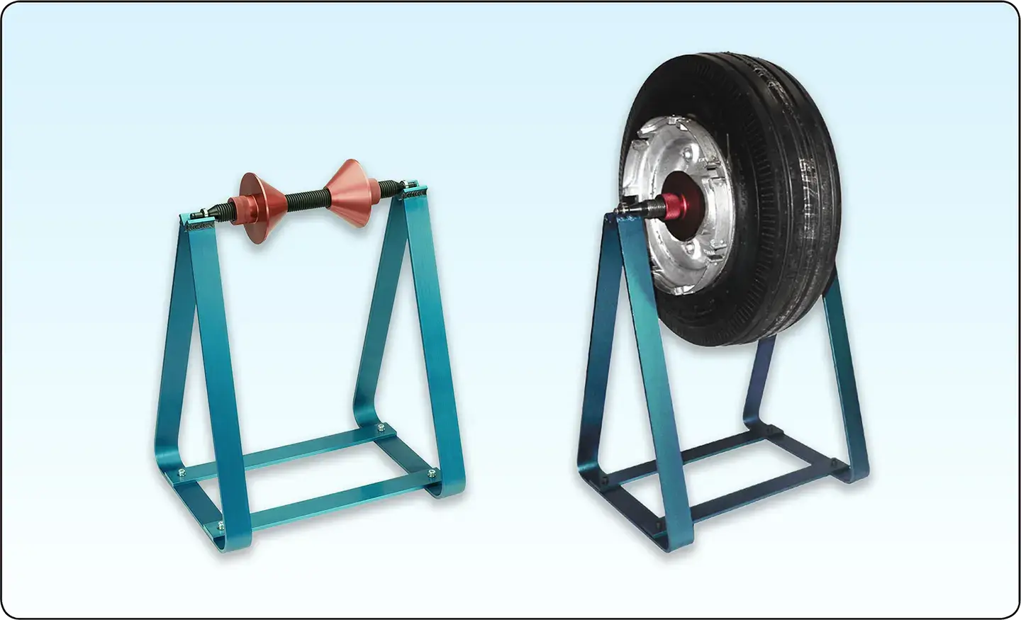 |
| Figure 34. A typical aircraft tire and wheel balancing stand |
 |
| Figure 35. A tire balancing patch (left), adhesive wheel weights (center), and a bolted wheel weight (right) are all used to balance aircraft tire and wheel assemblies per the manufacturer’s instructions |
Some aviation facilities offer dynamic balancing of aircraft tire and wheel assemblies. While this is rarely specified by manufacturers, a well balanced tire and wheel assembly helps provide shimmy free operation and reduces wear on brake and landing gear components, such as torque links.