Very early aircraft had no brake system to slow and stop the aircraft while it is on the ground. Instead, they rely on slow speeds, soft airfield surfaces, and the friction developed by the tail skid to reduce speed during ground operation. Brake systems designed for aircraft became common after World War I as the speed and complexity of aircraft increased and the use of smooth, paved runway surfaces proliferated. All modern aircraft are equipped with brakes. Their proper functioning is relied upon for safe operation of the aircraft on the ground. The brakes slow the aircraft and stop it in a reasonable amount of time. They hold the aircraft stationary during engine run-up and, in many cases, steer the aircraft during taxi. On most aircraft, each of the main wheels is equipped with a brake unit. The nose wheel or tail wheel does not have a brake.
In the typical brake system, mechanical and/or hydraulic linkages to the rudder pedals allow the pilot to control the brakes. Pushing on the top of the right rudder pedal activates the brake on the right main wheel(s) and pushing on the top of the left rudder pedal operates the brake on the left main wheel(s). The basic operation of brakes involves converting the kinetic energy of motion into heat energy through the creation of friction. A great amount of heat is developed and forces on the brake system components are demanding. Proper adjustment, inspection, and maintenance of the brakes is essential for effective operation.
Types and Construction of Aircraft Brakes
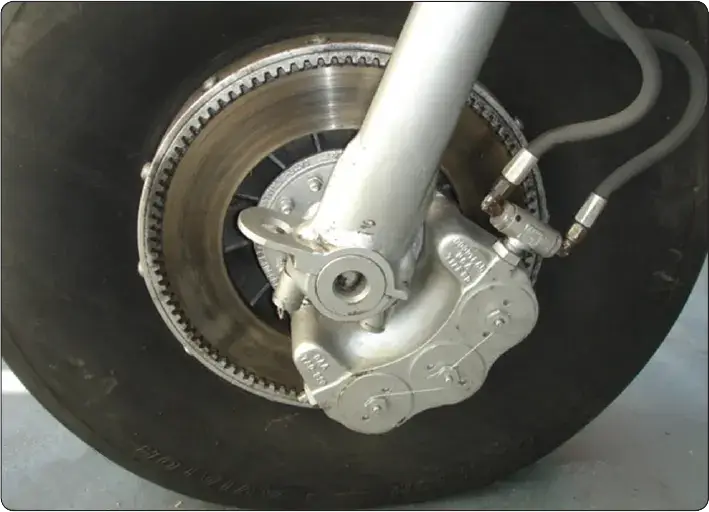
Modern aircraft typically use disc brakes. The disc rotates with the turning wheel assembly while a stationary caliper resists the rotation by causing friction against the disc when the brakes are applied. The size, weight, and landing speed of the aircraft influence the design and complexity of the disc brake system. Single, dual, and multiple disc brakes are common types of brakes. Segmented rotor brakes are used on large aircraft. Expander tube brakes are found on older large aircraft. The use of carbon discs is increasing in the modern aviation fleet.
Single Disc Brakes
Small, light aircraft typically achieve effective braking using a single disc keyed or bolted to each wheel. As the wheel turns, so does the disc. Braking is accomplished by applying friction to both sides of the disc from a non-rotating caliper bolted to the landing gear axle flange. Pistons in the caliper housing under hydraulic pressure force wearable brake pads or linings against the disc when the brakes are applied. Hydraulic master cylinders connected to the rudder pedals supply the pressure when the upper halves of the rudder pedals are pressed.
Floating Disc Brakes
A floating disc brake is illustrated in Figure 1. A more detailed, exploded view of this type of brake is shown in Figure 2. The caliper straddles the disc. It has three cylinders bored through the housing, but on other brakes this number may vary. Each cylinder accepts an actuating piston assembly comprised mainly of a piston, a return spring, and an automatic adjusting pin. Each brake assembly has six brake linings or pucks. Three are located on the ends of the pistons, which are in the outboard side of the caliper. They are designed to move in and out with the pistons and apply pressure to the outboard side of the disc. Three more linings are located opposite of these pucks on the inboard side of the caliper. These linings are stationary.
 |
| Figure 1. A single disc brake is a floating-disc, fixed caliper brake |
 |
| Figure 2. An exploded view of a single-disc brake assembly found on a light aircraft |
The brake disc is keyed to the wheel. It is free to move laterally in the key slots. This is known as a floating disc. When the brakes are applied, the pistons move out from the outboard cylinders and their pucks contact the disc. The disc slides slightly in the key slots until the inboard stationary pucks also contact the disc. The result is a fairly even amount of friction applied to each side of the disc and thus, the rotating motion is slowed.
When brake pressure is released, the return spring in each piston assembly forces the piston back away from the disc. The spring provides a preset clearance between each puck and the disc. The self-adjusting feature of the brake maintains the same clearance, regardless of the amount of wear on the brake pucks. The adjusting pin on the back of each piston moves with the piston through a frictional pin grip. When brake pressure is relieved, the force of the return spring is sufficient to move the piston back away from the brake disc, but not enough to move the adjusting pin held by the friction of the pin grip. The piston stops when it contacts the head of the adjusting pin. Thus, regardless of the amount of wear, the same travel of the piston is required to apply the brake. The stem of the pin protruding through the cylinder head serves as a wear indicator. The manufacturer’s maintenance information states the minimum length of the pin that needs to be protruding for the brakes to be considered airworthy. [Figure 3]
 |
| Figure 3. A cross-sectional view of a Goodyear single-disc brake caliper illustrates the adjusting pin assembly that doubles as a wear indicator |
The brake caliper has the necessary passages machined into it to facilitate hydraulic fluid movement and the application of pressure when the brakes are utilized. The caliper housing also contains a bleed port used by the technician to remove unwanted air from the system. Brake bleeding, as it is known, should be done in accordance with the manufacturer’s maintenance instructions.
Fixed-Disc Brakes
Even pressure must be applied to both sides of the brake disc to generate the required friction and obtain consistent wear properties from the brake linings. The floating disc accomplishes this as described above. It can also be accomplished by bolting the disc rigidly to the wheel and allowing the brake caliper and linings to float laterally when pressure is applied. This is the design of a common fixed-disc brake used on light aircraft. The brake is manufactured by the Cleveland Brake Company and is shown in Figure 4. An exploded detail view of the same type of brake is shown in Figure 5.
 |
| Figure 4. A Cleveland brake on a light aircraft is a fixed-disc brake. It allows the brake caliper to move laterally on anchor bolts to deliver even pressure to each side of the brake disc |
 |
| Figure 5. An exploded view of a dual-piston Cleveland brake assembly |
The fixed-disc, floating-caliper design allows the brake caliper and linings to adjust position in relationship to the disc. Linings are riveted to the pressure plate and backplate. Two anchor bolts that pass through the pressure plate are secured to the cylinder assembly. The other ends of the bolts are free to slide in and out of bushings in the torque plate, which is bolted to the axle flange. The cylinder assembly is bolted to the backplate to secure the assembly around the disc. When pressure is applied, the caliper and linings center on the disc via the sliding action of the anchor bolts in the torque plate bushings. This provides equal pressure to both sides of the disc to slow its rotation.
A unique feature of the Cleveland brake is that the linings can be replaced without removing the wheel. Unbolting the cylinder assembly from the backplate allows the anchor bolts to slide out of the torque plate bushings. The entire caliper assembly is then free and provides access to all of the components.
Maintenance requirements on all single disc brake systems are similar to those on brake systems of any type. Regular inspection for any damage and for wear on the linings and discs is required. Replacement of parts worn beyond limits is always followed by an operational check. The check is performed while taxiing the aircraft. The braking action for each main wheel should be equal with equal application of pedal pressure. Pedals should be firm, not soft or spongy, when applied. When pedal pressure is released, the brakes should release without any evidence of drag.
Dual-Disc Brakes
Dual-disc brakes are used on aircraft where a single disc on each wheel does not supply sufficient braking friction. Two discs are keyed to the wheel instead of one. A center carrier is located between the two discs. It contains linings on each side that contact each of the discs when the brakes are applied. The caliper mounting bolts are long and pass through the center carrier, as well as the backplate, which bolts to the housing assembly. [Figure 6]
 |
| Figure 6. A dual-disc brake is similar to a single-disc brake. It uses a center carrier to hold brake linings against each of the discs |
Multiple-Disc Brakes
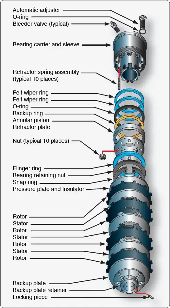
Large, heavy aircraft require the use of multiple-disc brakes. Multiple-disc brakes are heavy duty brakes designed for use with power brake control valves or power boost master cylinders, which is discussed later in this article. The brake assembly consists of an extended bearing carrier similar to a torque tube type unit that bolts to the axle flange. It supports the various brake parts, including an annular cylinder and piston, a series of steel discs alternating with copper or bronze-plated discs, a backplate, and a backplate retainer. The steel stators are keyed to the bearing carrier, and the copper or bronze plated rotors are keyed to the rotating wheel. Hydraulic pressure applied to the piston causes the entire stack of stators and rotors to be compressed. This creates enormous friction and heat and slows the rotation of the wheel. [Figure 7]
 |
| Figure 7. A multiple disc brake with bearing carrier upon which the parts of the brake are assembled including an annular cylinder and piston assembly that apply pressure evenly to a stack of rotors and stators |
As with the single and dual-disc brakes, retracting springs return the piston into the housing chamber of the bearing carrier when hydraulic pressure is relieved. The hydraulic fluid exits the brake to the return line through an automatic adjuster. The adjuster traps a predetermined amount of fluid in the brakes that is just sufficient to provide the correct clearances between the rotors and stators. [Figure 8] Brake wear is typically measured with a wear gauge that is not part of the brake assembly. These types of brakes are typically found on older transport category aircraft. The rotors and stators are relatively thin, only about 1/8-inch thick. They do not dissipate heat very well and have a tendency to warp.
 |
| Figure 8. A multiple-disc brake with details of the automatic adjuster |
Segmented Rotor-Disc Brakes
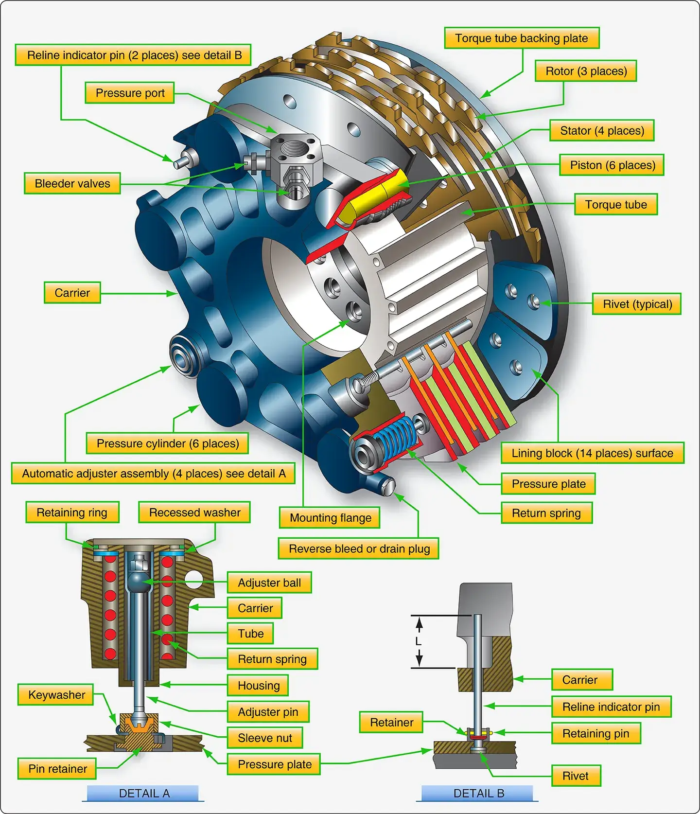
The large amount of heat generated while slowing the rotation of the wheels on large and high-performance aircraft is problematic. To better dissipate this heat, segmented rotor-disc brakes have been developed. Segmented rotor-disc brakes are multiple-disc brakes but of more modern design than the type discussed earlier. There are many variations. Most feature numerous elements that aid in the control and dissipation of heat. Segmented rotor-disc brakes are heavy-duty brakes especially adapted for use with the high-pressure hydraulic systems of power brake systems. Braking is accomplished by means of several sets of stationary, high friction type brake linings that make contact with rotating segments. The rotors are constructed with slots or in sections with space between them, which helps dissipate heat and give the brake its name. Segmented rotor multiple-disc brakes are the standard brake used on high performance and air carrier aircraft. An exploded view of one type of segmented rotor brake assembly is shown in Figure 9.
 |
| Figure 9. Exploded and detail views of segmented rotor brakes |
The description of a segmented rotor brake is very similar to the multiple-disc type brake previously described. The brake assembly consists of a carrier, a piston and piston cup seal, a pressure plate, an auxiliary stator plate, rotor segments, stator plates, automatic adjusters, and a backing plate.
The carrier assembly, or brake housing with torque tube, is the basic unit of the segmented rotor brake. It is the part that attaches to the landing gear shock strut flange upon which the other components of the brake are assembled. On some brakes, two grooves or cylinders are machined into the carrier to receive the piston cups and pistons. [Figure 9] Most segmented rotor-disc brakes have numerous individual cylinders machined into the brake housing into which fit the same number of actuating pistons. Often, these cylinders are supplied by two different hydraulic sources, alternating every other cylinder from a single source. If one source fails, the brake still operates sufficiently on the other. [Figure 10] External fittings in the carrier or brake housing admit the hydraulic fluid. A bleed port can also be found.
 |
| Figure 10. Many modern segmented rotor disc brakes use a housing machined to fit numerous individual actuating pistons |
A pressure plate is a flat, circular, high-strength steel, non-rotating plate notched on the inside circumference to fit over the stator drive sleeves or torque tube splines. The brake actuating pistons contact the pressure plate. Typically, an insulator is used between the piston head and the pressure plate to impede heat conduction from the brake discs. The pressure plate transfers the motion of the pistons to the stack of rotors and stators that compress to slow the rotation of the wheels. On most designs, brake lining material attached directly to the pressure plate contacts the first rotor in the stack to transfer the motion of the piston(s). [Figure 9] An auxiliary stator plate with brake lining material on the side opposite the pressure plate can also be used.
Any number of alternating rotors and stators are sandwiched under hydraulic pressure against the backing plate of the brake assembly when the brakes are applied. The backing plate is a heavy steel plate bolted to the housing or torque tube at a fixed dimension from the carrier housing. In most cases, it has brake lining material attached to it and contacts the last rotor in the stack. [Figure 9]
Stators are flat plates notched on the internal circumference to be held stationary by the torque tube splines. They have wearable brake lining material riveted or adhered to each side to make contact with adjacent rotors. The liner is typically constructed of numerous isolated blocks. [Figure 9] The space between the liner blocks aids in the dissipation of heat. The composition of the lining materials vary. Steel is often used.
Rotors are slit or segmented discs that have notches or tangs in the external circumference that key to the rotating wheel. Slots or spaces between sections of the rotor create segments that allow heat to dissipate faster than it would if the rotor was solid. They also allow for expansion and prevent warping. [Figure 9] Rotors are usually steel to which a frictional surface is bonded to both sides. Typically, sintered metal is used in creating the rotor contact surface.
Segmented multiple-disc brakes use retraction spring assemblies with auto clearance adjusters to pull the backplate away from the rotor and stator stack when brake pressure is removed. This provides clearance so the wheel can turn unimpeded by contact friction between the brake parts, but keeps the units in close proximity for rapid contact and braking when the brakes are applied. The number of retraction devices varies with brake design. Figure 11 illustrates a brake assembly used on a Boeing 737 transport category aircraft. In the cutaway view, the number and locations of the auto adjustment retraction mechanisms can be seen. Details of the mechanisms are also shown.
 |
| Figure 11. The multiple-disk brake assembly and details from a Boeing 737 |
Instead of using a pin grip assembly for auto adjustment, an adjuster pin, ball, and tube operate in the same manner. They move out when brake pressure is applied, but the ball in the tube limits the amount of the return to that equal to the brake lining wear. Two independent wear indicators are used on the brake illustrated. An indicator pin attached to the backplate protrudes through the carrier. The amount that it protrudes with the brakes applied is measured to ascertain if new linings are required.
Carbon Brakes
The segmented multiple-disc brake has given many years of reliable service to the aviation industry. It has evolved through time in an effort to make it lightweight and to dissipate the frictional heat of braking in a quick, safe manner. The latest iteration of the multiple-disc brake is the carbon-disc brake. It is currently found on high performance and air carrier aircraft. Carbon brakes are so named because carbon fiber materials are used to construct the brake rotors. [Figure 12]
 |
| Figure 12. A carbon brake for a Boeing 737 |
Carbon brakes are approximately forty percent lighter than conventional brakes. On a large transport category aircraft, this alone can save several hundred pounds in aircraft weight. The carbon fiber discs are noticeably thicker than sintered steel rotors but are extremely light. They are able to withstand temperatures fifty percent higher than steel component brakes. The maximum designed operating temperature is limited by the ability of adjacent components to withstand the high temperature. Carbon brakes have been shown to withstand two to three times the heat of a steel brake in non-aircraft applications. Carbon rotors also dissipate heat faster than steel rotors. A carbon rotor maintains its strength and dimensions at high temperatures. Moreover, carbon brakes last twenty to fifty percent longer than steel brakes, which results in reduced maintenance.
The only impediment to carbon brakes being used on all aircraft is the high cost of manufacturing. The price is expected to decrease as technology improves and greater numbers of aircraft operators enter the market.
Expander Tube Brakes
An expander tube brake is a different approach to braking that is used on aircraft of all sizes produced in the 1930s–1950s. It is a lightweight, low pressure brake bolted to the axle flange that fits inside an iron brake drum. A flat, fabric-reinforced neoprene tube is fitted around the circumference of a wheel-like torque flange. The exposed flat surface of the expander tube is lined with brake blocks similar to brake lining material. Two flat frames bolt to the sides of the torque flange. Tabs on the frames contain the tube and allow evenly spaced torque bars to be bolted in place across the tube between each brake block. These prevent circumferential movement of the tube on the flange. [Figure 13]
 |
| Figure 13. An expander tube brake assembly |
The expander tube is fitted with a metal nozzle on the inner surface. Hydraulic fluid under pressure is directed through this fitting into the inside of the tube when the brakes are applied. The tube expands outward, and the brake blocks make contact with the wheel drum causing friction that slows the wheel. As hydraulic pressure is increased, greater friction develops. Semi-elliptical springs located under the torque bars return the expander tube to a flat position around the flange when hydraulic pressure is removed. The clearance between the expander tube and the brake drum is adjustable by rotating an adjuster on some expander tube brakes. Consult the manufacturer’s maintenance manual for the correct clearance setting. Figure 14 gives an exploded view of an expander tube brake, detailing its components.
Expander tube brakes work well but have some drawbacks. They tend to take a setback when cold. They also have a tendency to swell with temperature and leak. They may drag inside the drum if this occurs. Eventually, expander brakes were abandoned in favor of disc brake systems.
 |
| Figure 14. An exploded view of an expander tube brake |
Brake Actuating Systems
The various brake assemblies, described in the previous section, all use hydraulic power to operate. Different means of delivering the required hydraulic fluid pressure to brake assemblies are discussed in this section.
There are three basic actuating systems:
- An independent system not part of the aircraft main hydraulic system;
- A booster system that uses the aircraft hydraulic system intermittently when needed; and
- A power brake system that only uses the aircraft main hydraulic system(s) as a source of pressure.
Systems on different aircraft vary, but the general operation is similar to those described.
Independent Master Cylinders
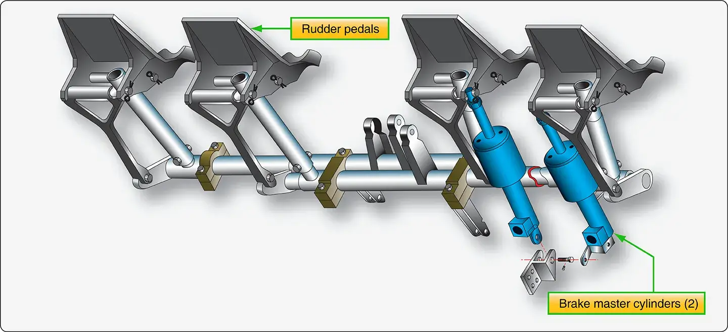
In general, small, light aircraft and aircraft without hydraulic systems use independent braking systems. An independent brake system is not connected in any way to the aircraft hydraulic system. Master cylinders are used to develop the necessary hydraulic pressure to operate the brakes. This is similar to the brake system of an automobile.
In most brake actuating systems, the pilot pushes on the tops of the rudder pedals to apply the brakes. A master cylinder for each brake is mechanically connected to the corresponding rudder pedal (i.e., right main brake to the right rudder pedal, left main brake to the left rudder pedal). [Figure 15] When the pedal is depressed, a piston inside a sealed fluid-filled chamber in the master cylinder forces hydraulic fluid through a line to the piston(s) in the brake assembly. The brake piston(s) push the brake linings against the brake rotor to create the friction that slows the wheel rotation. Pressure is increased throughout the entire brake system and against the rotor as the pedal is pushed harder.
 |
| Figure 15. Master cylinders on an independent brake system are directly connected to the rudder pedals or are connected through mechanical linkage |
Many master cylinders have built-in reservoirs for the brake hydraulic fluid. Others have a single remote reservoir that services both of the aircraft’s two master cylinders. [Figure 16] A few light aircraft with nose wheel steering have only one master cylinder that actuates both main wheel brakes. This is possible because steering the aircraft during taxi does not require differential braking. Regardless of the set-up, it is the master cylinder that builds up the pressure required for braking.
 |
| Figure 16. A remote reservoir services both master cylinders on some independent braking systems |
A master cylinder used with a remote reservoir is illustrated in Figure 17. This particular model is a Goodyear master cylinder. The cylinder is always filled with air-free, contaminant-free hydraulic fluid as is the reservoir and the line that connects the two together. When the top of the rudder pedal is depressed, the piston arm is mechanically moved forward into the master cylinder. It pushes the piston against the fluid, which is forced through the line to the brake. When pedal pressure is released, the return springs in the brake assembly retract the brake pistons back into the brake housing. The hydraulic fluid behind the pistons is displaced and must return to the master cylinder. As it does, a return spring in the master cylinder moves the piston, piston rod and rudder pedal back to the original position (brake off, pedal not depressed). The fluid behind the master cylinder piston flows back into the reservoir. The brake is ready to be applied again.
 |
| Figure 17. A Goodyear brake master cylinder from an independent braking system with a remote reservoir |
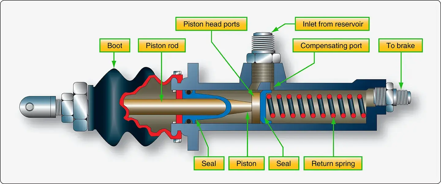
Hydraulic fluid expands as temperature increases. Trapped fluid can cause a brake to drag against the rotor(s). Leaks may also result. When the brakes are not applied, fluid must be allowed to expand safely without causing these issues. A compensating port is included in most master cylinders to facilitate this. In the master cylinder in Figure 17, this port is opened when the piston is fully retracted. Fluid in the brake system is allowed to expand into the reservoir, which has the capacity to accept the extra fluid volume. The typical reservoir is also vented to the atmosphere to maintain proper fluid supply pressure.
The forward side of the piston head contains a seal that closes off the compensating port when the brakes are applied so that pressure can build. The seal is only effective in the forward direction. When the piston is returning, or is fully retracted to the off position, fluid behind the piston is free to flow through piston head ports to replenish any fluid that may be lost downstream of the master cylinder. The aft end of the master cylinder contains a seal that prevents leakage at all times. A rubber boot fits over the piston rod and the aft end of the master cylinder to keep out dust.
A parking brake for this remote reservoir master cylinder brake system is a ratcheting mechanical device between the master cylinder and the rudder pedals. With the brakes applied, the ratchet is engaged by pulling the parking brake handle. To release the brakes, the rudder pedals are depressed further allowing the ratchet to disengage. With the parking brake set, any expansion of hydraulic fluid due to temperature is relieved by a spring in the mechanical linkage.
A common requirement of all braking systems is for there to be no air mixed in with the hydraulic fluid. Since air is compressible and hydraulic fluid essentially is not, any air under pressure when the brakes are applied causes spongy brakes. The pedals do not feel firm when pushed down due to the air compressing. Brake systems must be bled to remove all air from the system. Instructions for bleeding the brakes are in the manufacturer’s maintenance information. Brake systems equipped with Goodyear master cylinders must be bled from the top down to ensure any air trapped behind the master cylinder piston is removed.
An alternative common arrangement of independent braking systems incorporates two master cylinders, each with its own integral fluid reservoir. Except for the reservoir location, the brake system is basically the same as just described. The master cylinders are mechanically linked to the rudder pedals as before. Depressing the top of a pedal causes the piston rod to push the piston into the cylinder forcing the fluid out to the brake assembly. The piston rod rides in a compensator sleeve and contains an O-ring that seals the rod to the piston when the rod is moved forward. This blocks the compensating ports. When released, a spring returns the piston to its original position which refills the reservoir as it returns. The rod end seal retracts away from the piston head allowing a free flow of fluid from the cylinder through the compensating ports in the piston to the reservoir. [Figure 18]
 |
| Figure 18. A common master cylinder with built-in reservoir is shown. Illustration A depicts the master cylinder when the brakes are off. The compensating port is open to allow fluid to expand into the reservoir should temperature increase. In B, the brakes are applied. The piston rod-end seal covers the compensating port as it contacts the piston head |
The parking brake mechanism is a ratcheting type that operates as described. A servicing port is supplied at the top of the master cylinder reservoir. Typically, a vented plug is installed in the port to provide positive pressure on the fluid.
Boosted Brakes
In an independent braking system, the pressure applied to the brakes is only as great as the foot pressure applied to the top of the rudder pedal. Boosted brake actuating systems augment the force developed by the pilot with hydraulic system pressure when needed. The boost is only during heavy braking. It results in greater pressure applied to the brakes than the pilot alone can provide. Boosted brakes are used on medium and larger aircraft that do not require a full power brake actuating system.
A boosted brake master cylinder for each brake is mechanically attached to the rudder pedals. However, the boosted brake master cylinder operates differently. [Figure 19]
 |
| Figure 19. A master cylinder for a boosted brake system augments foot pedal pressure with aircraft system hydraulic pressure during heavy braking |
When the brakes are applied, the pressure from the pilot’s foot through the mechanical linkage moves the master cylinder piston in the direction to force fluid to the brakes. The initial movement closes the compensator poppet used to provide thermal expansion relief when the brakes are not applied. As the pilot pushes harder on the pedal, a spring loaded toggle moves a spool valve in the cylinder. Aircraft hydraulic system pressure flows through the valve to the back side of the piston. Pressure is increased, as is the force developed to apply the brakes.
When the pedal is released, the piston rod travels in the opposite direction, and the piston returns to the piston stop. The compensating poppet reopens. The toggle is withdrawn from the spool via linkages, and fluid pushes the spool back to expose the system return manifold port. System hydraulic fluid used to boost brake pressure returns through the port.
Power Brakes
Large and high performance aircraft are equipped with power brakes to slow, stop, and hold the aircraft. Power brake actuating systems use the aircraft hydraulic system as the source of power to apply the brakes. The pilot presses on the top of the rudder pedal for braking as with the other actuating systems. The volume and pressure of hydraulic fluid required cannot be produced by a master cylinder. Instead, a power brake control valve or brake metering valve receives the brake pedal input either directly or through linkages. The valve meters hydraulic fluid to the corresponding brake assembly in direct relation to the pressure applied to the pedal.
Many power brake system designs are in use. Most are similar to the simplified system illustrated in Figure 20-A. Power brake systems are constructed to facilitate graduated brake pressure control, brake pedal feel, and the necessary redundancy required in case of hydraulic system failure. Large aircraft brake systems integrate anti-skid detection and correction devices. These are necessary because wheel skid is difficult to detect on the flight deck without sensors. However, a skid can be quickly controlled automatically through pressure control of the hydraulic fluid to the brakes. Hydraulic fuses are also commonly found in power brake systems. The hostile environment around the landing gear increases the potential for a line to break or sever, a fitting to fail, or other hydraulic system malfunctions to occur where hydraulic fluid is lost en route to the brake assemblies. A fuse stops any excessive flow of fluid when detected by closing to retain the remaining fluid in the hydraulic system. Shuttle valves are used to direct flow from optional sources of fluid, such as in redundant systems or during the use of an emergency brake power source. An airliner power brake system is illustrated in Figure 20-B.
 |
| Figure 20. The orientation of components in a basic power brake system is shown in A. The general layout of an airliner power brake system is shown in B |
Brake Control Valve/Brake Metering Valve
The key element in a power brake system is the brake control valve, sometimes called a brake metering valve. It responds to brake pedal input by directing aircraft system hydraulic fluid to the brakes. As pressure is increased on the brake pedal, more fluid is directed to the brake causing a higher pressure and greater braking action.
A brake metering valve from a Boeing 737 is illustrated in Figure 21. The system in which it is installed is diagramed in Figure 22. Two sources of hydraulic pressure provide redundancy in this brake system. A brake input shaft, connected to the rudder/brake pedal through mechanical linkages, provides the position input to the metering valve. As in most brake control valves, the brake input shaft moves a tapered spool or slide in the valve so that it allows hydraulic system pressure to flow to the brakes. At the same time, the slide covers and uncovers access to the hydraulic system return port as required.
 |
| Figure 21. A brake metering valve from a Boeing 737. A machined slide or spool moves laterally to admit the correct amount of hydraulic system fluid to the brakes. The pressure developed is in proportion to the amount the rudder/brake pedal is depressed and the amount the slide is displaced. The slide/spool also simultaneously controls the return of fluid to the hydraulic system return manifold when brake pressure is released |
 |
| Figure 22. The power brake system on a Boeing 737 |
When the rudder/brake pedal is depressed, the slide in the metering valve moves to the left. [Figure 21] It covers the return port so pressure can build in the brake system. The hydraulic supply pressure chamber is connected to the brake system pressure chamber by the movement of the slide, which due to its taper, unblocks the passage between these two. As the pedal is depressed further, the valve slide moves farther to the left. This enables more fluid to flow to the brakes due to the narrowing shape of the slide. Brake pressure increases with the additional fluid. A passage in the slide directs brake pressure fluid into a compensating chamber at the end of the slide. This acts on the end of the slide creating a return force that counters the initial slide movement and gives feel to the brake pedal. As a result, the pressure and return ports are closed and pressure proportional to the foot pressure on the pedal is held on the brakes. When the pedal is released, a return spring and compensating chamber pressure drive the slide to the right into its original position (return port open, supply pressure chamber and brake pressure chambers blocked from each other).
The metering valve operates as described simultaneously for the inboard and the outboard brakes. [Figure 21] The design of the link assembly is such that a single side of the metering valve can operate even if the other fails. Most brake control valves and metering valves function in a similar manner, although many are single units that supply only one brake assembly.
The auto brake, referenced in the metering valve diagram, is connected into the landing gear retraction hydraulic line. Pressurized fluid enters this port and drives the slide slightly to the left to apply the brakes automatically after takeoff. This stops the wheels from rotating when retracted into the wheel wells. Auto brake pressure is withheld from this port when the landing gear is fully stowed since the retraction system is depressurized.
The majority of the rudder/brake pedal feel is supplied by the brake control or brake metering valve in a power brake system. Many aircraft refine the feel of the pedal with an additional feel unit. The brake valve feel augmentation unit, in the above system, uses a series of internal springs and pistons of various sizes to create a force on the brake input shaft movement. This provides feel back through the mechanical linkages consistent with the amount of rudder/ brake pedal applied. The request for light braking with slight pedal depression results in a light feel to the pedal and a harder resistance feel when the pedals are pushed harder during heavy braking. [Figure 23]
 |
| Figure 23. The power brake system on a Boeing 737 |
Emergency Brake Systems
As can be seen in Figure 22, the brake metering valves not only receive hydraulic pressure from two separate hydraulic systems, they also feed two separate brake assemblies. Each main wheel assembly has two wheels. The inboard wheel brake and the outboard wheel brake, located in their respective wheel rims, are independent from each other. In case of hydraulic system failure or brake failure, each is independently supplied to adequately slow and stop the aircraft without the other. More complicated aircraft may involve another hydraulic system for back-up or use a similar alternation of sources and brake assemblies to maintain braking in case of hydraulic system or brake failure.
In addition to supply system redundancy, the brake accumulator is also an emergency source of power for the brakes in many power brake systems. The accumulator is pre-charged with air or nitrogen on one side of its internal diaphragm. Enough hydraulic fluid is contained on the other side of the diaphragm to operate the brakes in case of an emergency. It is forced out of the accumulator into the brakes through the system lines under enough stored pressure to slow the aircraft. Typically, the accumulator is located upstream of the brake control/metering valve to capitalize on the control given by the valve. [Figure 24]
 |
| Figure 24. Emergency brake hydraulic fluid accumulators are precharged with nitrogen to deliver brake fluid to the brakes in the event normal and alternate hydraulic sources fail |
Some simpler power brake systems may use an emergency source of brake power that is delivered directly to the brake assemblies and bypasses the remainder of the brake system completely. A shuttle valve immediately upstream of the brake units shifts to accept this source when pressure is lost from the primary supply sources. Compressed air or nitrogen is sometimes used. A pre-charged fluid source can also be used as an alternate hydraulic source.
Parking Brake
The parking brake system function is a combined operation. The brakes are applied with the rudder pedals and a ratcheting system holds them in place when the parking brake lever on the flight deck is pulled. [Figure 25] At the same time, a shut-off valve is closed in the common return line from the brakes to the hydraulic system. This traps the fluid in the brakes holding the rotors stationary. Depressing the pedals further releases the pedal ratchet and opens the return line valve.
 |
| Figure 25. The parking brake lever on a Boeing 737 center pedestal throttle quadrant |
Brake Deboosters
Some aircraft brake assemblies that operate on aircraft hydraulic system pressure are not designed for such high pressure. They provide effective braking through a power brake system but require less than maximum hydraulic system pressure. To supply the lower pressure, a brake debooster cylinder is installed downstream of the control valve and anti-skid valve. [Figure 26] The debooster reduces all pressure from the control valve to within the working range of the brake assembly.
 |
| Figure 26. The location of a brake debooster cylinder on a landing gear strut and the debooster’s position in relation to other components of a power brake system |
Brake deboosters are simple devices that use the application of force over different sized pistons to reduce pressure. [Figure 27] Their operation can be understood through the application of the following equation:
Pressure = Force/Area
High-pressure hydraulic system input pressure acts on the small end of a piston. This develops a force proportional to the area of the piston head. The other end of the piston is larger and housed in a separate cylinder. The force from the smaller piston head is transferred to the larger area of the other end of the piston. The amount of pressure conveyed by the larger end of the piston is reduced due to the greater area over which the force is spread. The volume of output fluid increases since a larger piston and cylinder are used. The reduced pressure is delivered to the brake assembly.
 |
| Figure 27. Brake deboosters |
The spring in the debooster aids in returning the piston to the ready position. If fluid is lost downstream of the deboost cylinder, the piston travels further down into the cylinder when the brakes are applied. The pin unseats the ball and allows fluid into the lower cylinder to replace what was lost. Once replenished, the piston rises up in the cylinder due to pressure build-up. The ball reseats as the piston travels above the pin and normal braking resumes. This function is not meant to permit leaks in the brake assemblies. Any leak discovered must be repaired by the technician.
A lockout debooster functions as a debooster and a hydraulic fuse. If fluid is not encountered as the piston moves down in the cylinder, the flow of fluid to the brakes is stopped. This prevents the loss of all system hydraulic fluid should a rupture downstream of the debooster occur. Lockout deboosters have a handle to reset the device after it closes as a fuse. If not reset, no braking action is possible.
Anti-Skid
Large aircraft with power brakes require anti-skid systems. It is not possible to immediately ascertain in the flight deck when a wheel stops rotating and begins to skid, especially in aircraft with multiple-wheel main landing gear assemblies. A skid not corrected can quickly lead to a tire blowout, possible damage to the aircraft, and control of the aircraft may be lost.
System Operation
The anti-skid system not only detects wheel skid, it also detects when wheel skid is imminent. It automatically relieves pressure to the brake pistons of the wheel in question by momentarily connecting the pressurized brake fluid area to the hydraulic system return line. This allows the wheel to rotate and avoid a skid. Lower pressure is then maintained to the brake at a level that slows the wheel without causing it to skid.
Maximum braking efficiency exists when the wheels are decelerating at a maximum rate but are not skidding. If a wheel decelerates too fast, it is an indication that the brakes are about to lock and cause a skid. To ensure that this does not happen, each wheel is monitored for a deceleration rate faster than a preset rate. When excessive deceleration is detected, hydraulic pressure is reduced to the brake on that wheel. To operate the anti-skid system, flight deck switches must be placed in the ON position. [Figure 28] After the aircraft touches down, the pilot applies and holds full pressure to the rudder brake pedals. The anti-skid system then functions automatically until the speed of the aircraft has dropped to approximately 20 mph. The system returns to manual braking mode for slow taxi and ground maneuvering.
 |
| Figure 28. Antiskid switches in the cockpit |
There are various designs of anti-skid systems. Most contain three main types of components: wheel speed sensors, anti-skid control valves, and a control unit. These units work together without human interference. Some anti-skid systems provide complete automatic braking. The pilot needs only to turn on the auto brake system, and the anti-skid components slow the aircraft without pedal input. [Figure 28] Ground safety switches are wired into the circuitry for anti-skid and auto brake systems. Wheel speed sensors are located on each wheel equipped with a brake assembly. Each brake also has its own anti-skid control valve. Typically, a single control box contains the anti-skid control circuitry for all of the brakes on the aircraft. [Figure 29]
 |
| Figure 29. A wheel sensor (left), a control unit (center), and a control valve (right) are components of an antiskid system. A sensor is located on each wheel equipped with a brake assembly. An antiskid control valve for each brake assembly is controlled from a single central control unit |
Wheel Speed Sensors
Wheel speed sensors are transducers. They may be alternating current (AC) or direct current (DC). The typical AC wheel speed sensor has a stator mounted in the wheel axle. A coil around it is connected to a controlled DC source so that when energized, the stator becomes an electromagnet. A rotor that turns inside the stator is connected to the rotating wheel hub assembly through a drive coupling so that it rotates at the speed of the wheel. Lobes on the rotor and stator cause the distance between the two components to constantly change during rotation. This alters the magnetic coupling or reluctance between the rotor and stator. As the electromagnetic field changes, a variable frequency AC is induced in the stator coil. The frequency is directly proportional to the speed of rotation of the wheel. The AC signal is fed to the control unit for processing. A DC wheel speed sensor is similar, except that a DC output is produced the magnitude of which is directly proportional to wheel speed. [Figure 30]
 |
| Figure 30. The stator of an antiskid wheel sensor is mounted in the axle, and the rotor is coupled to the wheel hub spider that rotates with the wheel |
Control Units
The control unit can be regarded as the brain of the anti-skid system. It receives signals from each of the wheel sensors. Comparative circuits are used to determine if any of the signals indicate a skid is imminent or occurring on a particular wheel. If so, a signal is sent to the control valve of the wheel to relieve hydraulic pressure to that brake which prevents or relieves the skid. The control unit may or may not have external test switches and status indicating lights. It is common for it to be located in the avionics bay of the aircraft. [Figure 31]
 |
| Figure 31. A rack mounted antiskid control unit from an airliner |
The Boeing anti-skid control valve block diagram in Figure 32 gives further detail on the functions of an anti-skid control unit. Other aircraft may have different logic to achieve similar end results. DC systems do not require an input converter since DC is received from the wheel sensors, and the control unit circuitry operates primarily with DC. Only the functions on one circuit card for one wheel brake assembly are shown in Figure 32. Each wheel has its own identical circuitry card to facilitate simultaneous operation. All cards are housed in a single control unit that Boeing calls a control shield.
 |
| Figure 32. A Boeing 737 antiskid control unit internal block diagram |
The converter shown changes the AC frequency received from the wheel sensor into DC voltage that is proportional to wheel speed. The output is used in a velocity reference loop that contains deceleration and velocity reference circuits. The converter also supplies input for the spoiler system and the locked wheel system, which is discussed at the end of this section. A velocity reference loop output voltage is produced, which represents the instantaneous velocity of the aircraft. This is compared to converter output in the velocity comparator. This comparison of voltages is essentially the comparison of the aircraft speed to wheel speed. The output from the velocity comparator is a positive or negative error voltage corresponding to whether the wheel speed is too fast or too slow for optimum braking efficiency for a given aircraft speed.
The error output voltage from the comparator feeds the pressure bias modulator circuit. This is a memory circuit that establishes a threshold where the pressure to the brakes provides optimum braking. The error voltage causes the modulator to either increase or decrease the pressure to the brakes in attempt to hold the modulator threshold. It produces a voltage output that is sent to the summing amplifier to do this. A lead output from the comparator anticipates when the tire is about to skid with a voltage that decreases the pressure to the brake. It sends this voltage to the summing amplifier as well. A transient control output from the comparator designed for rapid pressure dump when a sudden skid has occurred also sends voltage to the summing amp. As the name suggests, the input voltages to the amplifier are summed, and a composite voltage is sent to the valve driver. The driver prepares the current required to be sent to the control valve to adjust the position of the valve. Brake pressure increases, decreases, or holds steady depending on this value.
Anti-Skid Control Valves
Anti-skid control valves are fast-acting, electrically controlled hydraulic valves that respond to the input from the anti-skid control unit. There is one control valve for each brake assembly. A torque motor uses the input from the valve driver to adjust the position of a flapper between two nozzles. By moving the flapper closer to one nozzle or the other, pressures are developed in the second stage of the valve. These pressures act on a spool that is positioned to build or reduce pressure to the brake by opening and blocking fluid ports. [Figure 33]
 |
| Figure 33. An antiskid control valve uses a torque motor controlled flapper in the first stage of the valve to adjust pressure on a spool in the second stage of the valve to build or relieve pressure to the brake |
As pressure is adjusted to the brakes, deceleration slows to within the range that provides the most effective braking without skidding. The wheel sensor signal adjusts to the wheel speed, and the control unit processes the change. Output is altered to the control valve. The control valve flapper position is adjusted and steady braking resumes without correction until needed. Anti-skid control valves are typically located in the main wheel for close access to hydraulic pressure and return manifolds, as well as the brake assemblies. [Figure 34] Systematically, they are positioned downstream of the power brake control valves but upstream of debooster cylinders if the aircraft is so equipped as was shown in Figure 26.
 |
| Figure 34. Two antiskid control valves with associated plumbing and wiring |
Touchdown and Lock Wheel Protection
It is essential that the brakes are not applied when the aircraft contacts the runway upon landing. This could cause immediate tire blowout. A touchdown protection mode is built into most aircraft anti-skid systems to prevent this. It typically functions in conjunction with the wheel speed sensor and the air/ground safety switch on the landing gear strut (squat switch). Until the aircraft has weight on wheels, the detector circuitry signals the anti-skid control valve to open the passage between the brakes and the hydraulic system return, thus preventing pressure build-up and application of the brakes. Once the squat switch is open, the anti-skid control unit sends a signal to the control valve to close and permit brake pressure build-up. As a back-up and when the aircraft is on the ground with the strut not compressed enough to open the squat switch, a minimum wheel speed sensor signal can override and allow braking. Wheels are often grouped with one relying on the squat switch and the other on wheel speed sensor output to ensure braking when the aircraft is on the ground, but not before then.
Locked wheel protection recognizes if a wheel is not rotating. When this occurs, the anti-skid control valve is signaled to fully open. Some aircraft anti-skid control logic, such as the Boeing 737 shown in Figure 33, expands the locked wheel function. Comparator circuitry is used to relieve pressure when one wheel of a paired group of wheels rotates 25 percent slower than the other. Inboard and outboard pairs are used because if one of the pair is rotating at a certain speed, so should the other. If it is not, a skid is beginning or has occurred.
On takeoff, the anti-skid system receives input through a switch located on the gear selector that shuts off the anti-skid system. This allows the brakes to be applied as retraction occurs so that no wheel rotation exists while the gear is stowed.
Auto Brakes
Aircraft equipped with auto brakes typically bypass the brake control valves or brake metering valves and use a separate auto brake control valve to provide this function. In addition to the redundancy provided, auto brakes rely on the anti-skid system to adjust pressure to the brakes if required due to an impending skid. Figure 35 shows a simplified diagram of the Boeing 757 brake system with the auto brake valve in relation to the main metering valve and anti-skid valves in this eight-main wheel system.
 |
| Figure 35. The Boeing 757 normal brake system with auto brake and antiskid |
Anti-Skid System Tests
It is important to know the status of the anti-skid system prior to attempting to use it during a landing or aborted takeoff. Ground tests and in-flight tests are used. Built-in test circuits and control features allow testing of the system components and provide warnings should a particular component or part of the system become inoperative. An inoperative anti-skid system can be shut off without affecting normal brake operation.
Ground Test
Ground tests vary slightly from aircraft to aircraft. Consult the manufacturer’s maintenance manual for test procedures specific to the aircraft in question.
Much of the anti-skid system testing originates from testing circuits in the anti-skid control unit. Built-in test circuits continuously monitor the anti-skid system and provide warning if a failure occurs. An operational test can be performed before flight. The anti-skid control switch and/or test switch is used in conjunction with system indicator light(s) to determine system integrity. A test is first done with the aircraft at rest and then in an electrically simulated anti-skid braking condition. Some anti-skid control units contain system and component testing switches and lights for use by the technician. This accomplishes the same operational verification, but allows an additional degree of troubleshooting. Test sets are available for anti-skid systems that produce electric signals that simulate speed outputs of the wheel transducer, deceleration rates, and flight/ground parameters.
In-Flight Test
In-flight testing of the anti-skid system is desirable and part of the pre-landing checklist so that the pilot is aware of system capability before landing. As with ground testing, a combination of switch positions and indicator lights are used according to information in the aircraft operations manual.
Anti-Skid System Maintenance
Anti-skid components require little maintenance. Troubleshooting anti-skid system faults is either performed via test circuitry or can be accomplished through isolation of the fault to one of the three main operating components of the system. Anti-skid components are normally not repaired in the field. They are sent to the manufacturer or a certified repair station when work is required. Reported anti-skid system malfunctions are sometimes actually malfunctions of the brake system or brake assemblies. Ensure brake assemblies are bled and functioning normally without leaks before attempting to isolate problems in the anti-skid system.
Wheel Speed Sensor
Wheel speed sensors must be securely and correctly mounted in the axle. The means of keeping contamination out of the sensor, such as sealant or a hub cap, should be in place and in good condition. The wiring to the sensor is subject to harsh conditions and should be inspected for integrity and security. It should be repaired or replaced if damaged in accordance with the manufacturer’s instructions. Accessing the wheel speed sensor and spinning it by hand or other recommended device to ensure brakes apply and release via the anti-skid system is common practice.
Control Valve
Anti-skid control valve and hydraulic system filters should be cleaned or replaced at the prescribed intervals. Follow all manufacturer’s instructions when performing this maintenance. Wiring to the valve must be secure, and there should be no fluid leaks.
Control Unit
Control units should be securely mounted. Test switches and indicators, if any, should be in place and functioning. It is essential that wiring to the control unit is secure. A wide variety of control units are in use. Follow the manufacturer’s instructions at all times when inspecting or attempting to perform maintenance on these units.