Modern aircraft increasingly employs digital electronics in avionics rather than analog electronics. Transistors are used in digital electronics to construct circuits that act as digital logic gates. The purpose and task of a device is achieved by manipulating electric signals through the logic gates. Thousands, and even millions, of tiny transistors can be placed on a chip to create the digital logic landscape through which a component’s signals are processed.
Digital Building Blocks
Digital logic is based on the binary number system. There are two conditions than may exist, 1 or 0. In a digital circuit, these are equivalent to voltage or no voltage. Within the binary system, these two conditions are called Logic 1 and Logic 0. Using just these two conditions, gates can be constructed to manipulate information. There are a handful of common logic gates that are used. By combining any number of these tiny solid-state gates, significant memorization, manipulation, and calculation of information can be performed.The NOT Gate
The NOT gate is the simplest of all gates. If the input to the gate is Logic 1, then the output is NOT Logic 1. This means that it is Logic 0, since there are only two conditions in the binary world. In an electronic circuit, a NOT gate would invert the input signal. In other words, if there was voltage at the input to the gate, there would be no output voltage. The gate can be constructed with transistors and resistors to yield this electrical logic every time. (The gate or circuit would also have to invert an input of Logic 0 into an output of Logic 1.)To understand logic gates, truth tables are often used. A truth table gives all of the possibilities in binary terms for each gate containing a characteristic logic function. For example, a truth table for a NOT gate is illustrated in Figure 1. Any input (A) is NOT present at the output (B). This is simple, but it defines this logic situation. A tiny NOT gate circuit can be built using transistors that produce these results. In other words, a circuit can be built such that if voltage arrives at the gate, no voltage is output or vice-versa.
 |
| Figure 1. A NOT logic gate symbol and a NOT gate truth table |
When using transistors to build logic gates, the primary concern is to operate them within the circuits so the transistors are either OFF (not conducting) or fully ON (saturated). In this manner, reliable logic functions can be performed. The variable voltage and current situations present during the active mode of the transistor are of less importance.
Figure 2 illustrates an electronic circuit diagram that performs the logic NOT gate function. Any input, either a no voltage or voltage condition, yields the opposite output. This gate is built with bipolar junction transistors, resistors, and a few diodes. Other designs exist that may have different components.
 |
| Figure 2. An electronic circuit that reliably performs the NOT logic function |
When examining and discussing digital electronic circuits, the electronic circuit design of a gate is usually not presented. The symbol for the logic gate is most often used. [Figure 1] The technician can then concentrate on the configuration of the logic gates in relation to each other. A brief discussion of the other logic gates, their symbols, and truth tables follow.
Buffer Gate
Another logic gate with only one input and one output is the buffer. It is a gate with the same output as the input. While this may seem redundant or useless, an amplifier may be considered a buffer in a digital circuit because if there is voltage present at the input, there is an output voltage. If there is no voltage at the input, there is no output voltage. When used as an amplifier, the buffer can change the values of a signal. This is often done to stabilize a weak or varying signal. All gates are amplifiers subject to output fluctuations. The buffer steadies the output of the upstream device while maintaining its basic characteristic. Another application of a buffer that is two NOT gates, is to use it to isolate a portion of a circuit. [Figure 3] |
| Figure 3. A buffer or amplifier symbol and the truth table of the buffer, which is actually two consecutive NOT gates |
AND Gate
Most common logic gates have two inputs. Three or more inputs are possible on some gates. When considering the characteristics of any logic gate, an output of Logic 1 is sought and a condition for the inputs is stated or examined. For example, Figure 4 illustrates an AND gate. For an AND gate to have a Logic 1 output, both inputs have to be Logic 1. In an actual electronic circuit, this means that for a voltage to be present at the output, the AND gate circuit has to receive voltage at both of its inputs. As pointed out, there are different arrangements of electronic components that yield this result. Whichever is used is summarized and presented as the AND gate symbol. The truth table in Figure 4 illustrates that there is only one way to have an output of Logic 1 or voltage when using an AND gate. |
| Figure 4. An AND gate symbol and its truth table |
OR Gate
Another useful and common logic gate is the OR gate. In an OR gate, to have an output of Logic 1 (voltage present), one of the inputs must be Logic 1. As seen in Figure 5, only one of the inputs needs to be Logic 1 for there to be an output of Logic 1. When both inputs are Logic 1, the OR gate has a Logic 1 output because it still meets the condition of one of the inputs being Logic 1. |
| Figure 5. An OR gate symbol and its truth table |
NAND Gate
The AND, OR, and NOT gates are the basic logic gates. A few other logic gates are also useful. They can be derived from combining the AND, OR, and NOT gates. The NAND gate is a combination of an AND gate and a NOT gate. This means that AND gate conditions must be met and then inverted. So, the NAND gate is an AND gate followed by a NOT gate. The truth table for a NAND gate is shown in Figure 6 along with its symbol. If a Logic 1 output is to exist from a NAND gate, inputs A and B must not both be Logic 1. Or, if a NAND gate has both inputs Logic 1, the output is Logic 0. Stated in electronic terms, if there is to be an output voltage, then the inputs cannot both have voltage or, if both inputs have voltage, there is no output voltage. |
| Figure 6. A NAND gate symbol and its truth table illustrating that the NAND gate is an inverted AND gate |
NOTE: The values in the output column of the NAND gate table are exactly the opposite of the output values in the AND gate truth table.
NOR Gate
A NOR gate is similarly arranged except that it is an inverted OR gate. If there is to be a Logic 1 output, or output voltage, then neither input can be Logic 1 or have input voltage. This is the same as satisfying the OR gate conditions and then putting output through a NOT gate. The NOR gate truth table in Figure 7 shows that the NOR gate output values are exactly the opposite of the OR gate output values. |
| Figure 7. A NOR gate symbol and its truth table illustrating that the NOR gate is an inverted OR gate |
The NAND gate and the NOR gate have a unique distinction. Each one can be the only gate used in circuitry to produce the same output as any of the other logic gates. While it may be inefficient, it is testimonial to the flexibility that designers have when working with logic gates, the NAND and NOR gates in particular.
EXCLUSIVE OR Gate
Another common logic gate is the EXCLUSIVE OR gate. It is the same as an OR gate except for the condition where both inputs are Logic 1. In an OR gate, there would be Logic 1 output when both inputs are Logic 1. This is not allowed in an EXCLUSIVE OR gate. When either of the inputs is Logic 1, the output is Logic 1. But, if both inputs are logic 1, the Logic 1 output is excluded or Logic 0. [Figure 8] |
| Figure 8. An EXCLUSIVE OR gate symbol and its truth table, which is similar to an OR gate but excludes output when both inputs are the same |
Negative Logic Gates
There are also negative logic gates. The negative OR and the negative AND gates are gates wherein the inputs are inverted rather than inverting the output. This creates a unique set of outputs as seen in the truth tables in Figure 9. The negative OR gate is not the same as the NOR gate as is sometimes misunderstood. Neither is the negative AND gate the same as the NAND gate. However, as the truth tables reveal, the output of a negative AND gate is the same as a NOR gate, and the output of a negative OR gate is the same as a NAND gate. |
| Figure 9. The NEGATIVE AND gate symbol and its truth table (A) and the NEGATIVE OR gate symbol and truth table (B). The inputs are inverted in the NEGATIVE gates |
In summary, electronic circuits use transistors to construct logic gates that produce outputs related to the inputs shown in the truth tables for each kind of gate. The gates are then assembled with other components to manipulate data in digital circuits. The electronic digital signals used are voltage or no voltage representations of Logic 1 or Logic 0 conditions. By using a series of voltage output or no voltage output gates, manipulation, computation, and storage of data takes place.
Digital Aircraft Systems
Digital aircraft systems are the present and future of aviation. From communication and navigation to engine and flight controls, increased proliferation of digital technology increases reliability and performance. Processing, storing, and transferring vital information for the operation of an aircraft in digital form provides a usable common language for monitoring, control, and safety. Integration of information from different systems is simplified. Self-monitoring, built-in test equipment (BITE) and air-to-ground data links increase maintenance efficiency. Digital buss networking allows aircraft system computers to interact for a coordinated comprehensive approach to flight operations.Digital Data Displays
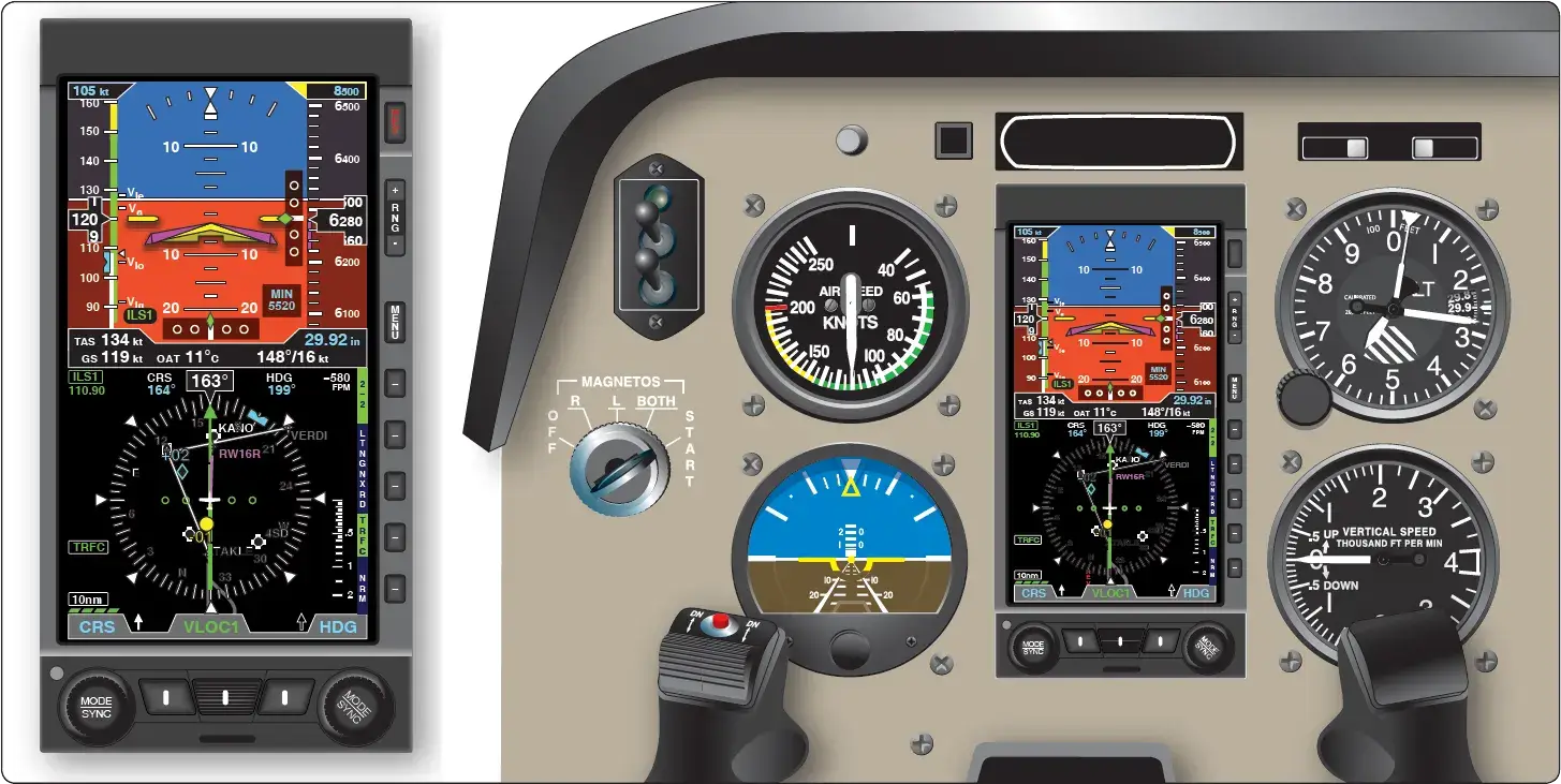
Modern digital data displays are the most visible features of digital aircraft systems. They extend the functional advantages of state of the art digital communication and navigation avionics and other digital aircraft systems via the use of an enhanced interface with the pilot. The result is an increase in situational awareness and overall safety of flight. Digital data displays are the glass of the glass cockpit. They expand the amount, clarity, and proximity of the information presented to the pilot. [Figure 10] |
| Figure 10. A modern glass cockpit on a general aviation aircraft. Digital data displays replace many older instruments and indicators of the past |
Many digital data displays are available from numerous manufacturers as original equipment in new aircraft, or as retrofit components or complete retrofit systems for older aircraft. Approval for retrofit displays is usually accomplished through supplementary type certificate (STC) awarded to the equipment manufacturer.
Early digital displays presented scale indication in digital or integer format readouts. Today’s digital data displays are analogous to computer screen presentations. Numerous aircraft and flight instrument readouts and symbolic presentations are combined with communication and navigational information on multifunctional displays (MFD).
Often a display has a main function with potential to back-up another display should it fail. Names, such as primary flight display (PFD), secondary flight display, navigational display (ND), etc., are often used to describe a display by its primary use. The hardware composition of the displays is essentially the same. Avionics components and computers combine to provide the different information portrayed on the displays.
Controls on the instrument panel or on the display unit itself are used for selection. Some screens have limited display capability because they are not part of a totally integrated system; however, they are extremely powerful electronic units with wide capability. [Figure 11]
 |
| Figure 11. A retrofit digital data display |
The basis of the information displayed on what is known as a PFD, is usually an electronic flight instrument system (EFIS) like representation of the aircraft attitude indicator in the upper half of the display, and an electronic horizontal situation indicator display on the lower half. Numerous ancillary readouts are integrated or surround the electronic attitude indicator and the horizontal situation indicator (HSI). On full glass cockpit PFDs, all of the basic T instrument indications are presented and much more, such as communication and navigation information, weather data, terrain features, and approach information. Data displays for engine parameters, hydraulics, fuel, and other airframe systems are often displayed on the secondary flight display or on an independent display made for this purpose. [Figure 12]
 |
| Figure 12. A digital data display dedicated to the depiction of engine and airframe system parameter status |
As with other avionics components, repair and maintenance of the internal components of digital data displays is reserved for licensed repair stations only.
Digital Tuners and Audio Panels
Numerous communication and navigation devices are described in the Aviation Communication and Navigation section. Many of these use radio waves and must be tuned to a desired frequency for operation. As a flight progresses, retuning and changing from one piece of equipment to another can occur frequently. An audio panel or digital tuner consolidates various communication and navigation radio selection controls into a single unit. The pilot can select and use, or select and tune, most of the aircraft’s avionics from this one control interface. [Figure 13] |
| Figure 13. An audio panel in a general aviation aircraft integrates the selection of several radio-based communication and navigational aids into a single control panel (left). A digital tuner (right) does the same on a business class aircraft and allows the frequency of each device to be tuned from the same panel as well |
- Electron Control Valves (Analog Electronics (Part 1)
- Basic Analog Circuits (Analog Electronics (Part 2)
- History of Avionics
- Analog Versus Digital Electronics
- Radio Communication
- Radio Navigation
- VOR Navigation System
- Automatic Direction Finder (ADF)