One of the oldest and most useful navigational aids is the very high frequency omni-directional range (VOR) navigation system. The four main components of a typical system are: a receiver, a visual indicator, a frequency selector (controller or control panel), and antennas.
The system was developed after World War II and is still in use today. It consists of thousands of land-based transmitter stations, or VORs, that communicate with radio receiving equipment on board aircraft. Many of the VORs are located along airways.
The Victor airway system is built around the VOR navigation system. Ground VOR transmitter units are also located at airports where they are known as TVOR (terminal VOR).
The U.S. Military has a navigational system known as TACAN that operates similarly to the VOR system. Sometimes VOR and TACAN transmitters share a location. These sites are known as VORTACs.
The position of all VORs, TVORs, and VORTACs are marked on aeronautical charts along with the name of the station, the frequency to which an airborne receiver must be tuned to use the station, and a Morse code designation for the station.
Some VORs also broadcast a voice identifier on a separate frequency that is included on the chart. [Figure 1]
 |
| Figure 1. A VOR ground station |
VOR uses VHF radio waves (108–117.95 MHz) with 50 kHz separation between each channel. This keeps atmospheric interference to a minimum but limits the VOR to line-of-sight usage. To receive VOR VHF radio waves, generally a V-shaped, horizontally polarized, dipole antenna is used. Other types of antennas are also certified. Follow the manufacturer’s instructions for installation location. [Figure 2]
 |
| Figure 2. V-shaped, horizontally polarized, dipole antennas are commonly used for VOR and VOR/glideslope reception. All antenna shown are VOR/glideslope antenna |
The signals produced by a VOR transmitter propagate 360° from the unit and are used by aircraft to navigate to and from the station with the help of an onboard VOR receiver and display instruments.
A pilot is not required to fly a pattern to intersect the signal from a VOR station since it propagates out in every direction. The radio waves are received as long as the aircraft is in range of the ground unit and regardless of the aircraft’s direction of travel. [Figure 3]
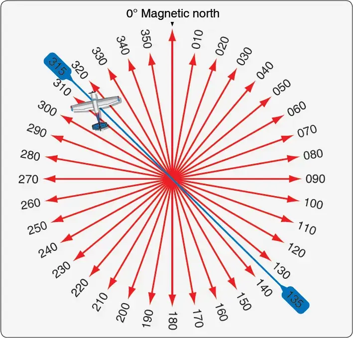 |
| Figure 3. A VOR transmitter produces signals for 360° radials that an airborne receiver uses to indicate the aircraft’s location in relation to the VOR station regardless of the aircraft’s direction of flight. The aircraft shown is on the 315° radial even though it does not have a heading of 315° |
A VOR transmitter produces two signals that a receiver on board an aircraft uses to locate itself in relation to the ground station. One signal is a reference signal. The second is produced by electronically rotating a variable signal. The variable signal is in phase with the reference signal when at magnetic north but becomes increasingly out of phase as it is rotated to 180°.
As it continues to rotate to 360° (0°), the signals become increasingly in phase until they are in phase again at magnetic north. The receiver in the aircraft deciphers the phase difference and determines the aircraft’s position in degrees from the VOR ground-based unit. [Figure 4]
 |
| Figure 4. The phase relationship of the two broadcast VOR signals |
Most aircraft carry a dual VOR receiver. Sometimes, the VOR receivers are part of the same avionics unit as the VHF communication transceiver(s). These are known as NAV/COM radios. Internal components are shared since frequency bands for each are adjacent. [Figure 5]
 |
| Figure 5. A NAV/COM receiver typically found in light aircraft |
Large aircraft may have two dual receivers and even dual antennas. Normally, one receiver is selected for use and the second is tuned to the frequency of the next VOR station to be encountered en route. A means for switching between NAV 1 and NAV 2 is provided as is a switch for selecting the active or standby frequency. [Figure 6] VOR receivers are also found coupled with instrument landing system (ILS) receivers and glideslope receivers.
 |
| Figure 6. An airliner VOR control head with two independent NAV receivers each with an active and standby tuning circuit controlled by a toggle switch |
A VOR receiver interprets the bearing in degrees to (or from) the VOR station where the signals are generated. It also produces DC voltage to drive the display of the deviation from the desired course centerline to (or from) the selected station.
Additionally, the receiver decides whether or not the aircraft is flying toward the VOR or away from it. These items can be displayed a number of different ways on various instruments. Older aircraft are often equipped with a VOR gauge dedicated to display only VOR information. This is also called an omni-bearing selector (OBS) or a course deviation indicator (CDI). [Figure 7]
 |
| Figure 7. A traditional VOR gauge, also known as a course deviation indicator (CDI) or an omni-bearing selector (OBS) |
The CDI linear indicator remains essentially vertical but moves left and right across the graduations on the instrument face to show deviation from being on course. Each graduation represents 2°. The OBS knob rotates the azimuth ring. When in range of a VOR, the pilot rotates the OBS until the course deviation indicator centers.
For each location of an aircraft, the OBS can be rotated to two positions where the CDI will center. One selection produces an arrow in the TO window of the gauge indicating that the aircraft is traveling toward the VOR station. The other selectable bearing is 180° from this. When chosen, the arrow is displayed in the FROM window indicating the aircraft is moving away from the VOR on the course selected.
The pilot must steer the aircraft to maintain the selected course with the CDI centered to fly directly to or from the VOR. The displayed VOR information is derived from deciphering the phase relationship between the two simultaneously transmitted signals from the VOR ground station. When power is lost or the VOR signal is weak or interrupted, a NAV warning flag comes into view. [Figure 7]
A separate gauge for the VOR information is not always used. As flight instruments and displays have evolved, VOR navigation information has been integrated into other instrument displays, such as the radio magnetic indicator (RMI), the HSI, an EFIS display or an electronic attitude director indicator (EADI).
Flight management systems and automatic flight control systems are also made to integrate VOR information to automatically control the aircraft on its planned flight segments. Flat panel MFDs integrate VOR information into moving map presentations and other selected displays. The basic information of the radial bearing in degrees, course deviation indication, and to/from information remains unchanged, however. [Figure 8]
 |
| Figure 8. A mechanical HSI (left) and an electronic HSI (right) both display VOR information |
At large airports, an instrument landing system (ILS) guides the aircraft to the runway while on an instrument landing approach. The aircraft’s VOR receiver is used to interpret the radio signals. It produces a more sensitive course deviation indication on the same instrument display as the VOR CDI display.
This part of the ILS is known as the localizer and is discussed below. While tuned to the ILS localizer frequency, the VOR circuitry of the VOR/ILS receiver is inactive.
It is common at VOR stations to combine the VOR transmitter with distance measuring equipment (DME) or a nondirectional beacon (NDB) such as an ADF transmitter and antenna. When used with a DME, pilots can gain an exact fix on the aircraft’s location using the VOR and DME together.
Since the VOR indicates the aircraft’s bearing to the VOR transmitter and a co-located DME indicates how far away the station is, this relieves the pilot from having to fly over the station to know with certainty their location. These navigational aids are discussed separately in the following sections.
Functional accuracy of VOR equipment is critical to the safety of flight. VOR receivers are operationally tested using VOR test facilities (VOT). These are located at numerous airports that can be identified in the Airport Facilities Directory for the area concerned.
Specific points on the airport surface are given to perform the test. Most VOTs require tuning 108.0 MHz on the VOR receiver and centering the CDI. The OBS should indicate 0° showing FROM on the indicator or 180° when showing TO. If an RMI is used as the indicator, the test heading should always indicate 180°.
Some repair stations can also generate signals to test VOR receivers although not on 108.0 MHz. Contact the repair station for the transmission frequency and for their assistance in checking the VOR system. A logbook entry is required.
An error of ±4° should not be exceeded when testing a VOR system with a VOT. An error in excess of this prevents the use of the aircraft for IFR fights until repairs are made. Aircraft having dual VOR systems where only the antenna is shared may be tested by comparing the output of each system to the other. Tune the VOR receivers to the local ground VOR station. A bearing indication difference of no more than ±4° is permissible.
How does a VOR receiver determine the aircraft's position?
What is the difference between a VORTAC and a TVOR?
What are the allowable error tolerances for VOR operational checks?
How does a Course Deviation Indicator (CDI) show course errors?
RELATED POSTS