An ILS is used to land an aircraft when visibility is poor. This radio navigation system guides the aircraft down a slope to the touchdown area on the runway. Multiple radio transmissions are used that enable an exact approach to landing with an ILS.
A localizer is one of the radio transmissions. It is used to provide horizontal guidance to the centerline of the runway. A separate glideslope broadcast provides vertical guidance of the aircraft down the proper glidepath to the touchdown point.
Compass locator transmissions for outer and middle approach marker beacons aid the pilot in intercepting the approach navigational aid system.
Marker beacons provide distance-from-the-runway information. Together, all of these radio signals make an ILS a very accurate and reliable means for landing aircraft. [Figure 1]
 |
| Figure 1. Components of an instrument landing system (ILS) |
Localizer
The localizer broadcast is a VHF broadcast in the lower range of the VOR frequencies (108 MHz–111.95 MHz) on odd frequencies only. Two modulated signals are produced from a horizontally polarized antenna complex beyond the far end of the approach runway. They create an expanding field that is 21⁄2° wide (about 1,500 feet) 5 miles from the runway.
The field tapers to runway width near the landing threshold. The left side of the approach area is filled with a VHF carrier wave modulated with a 90 Hz signal. The right side of the approach contains a 150 Hz modulated signal. The aircraft’s VOR receiver is tuned to the localizer VHF frequency that can be found on published approach plates and aeronautical charts.
The circuitry specific to standard VOR reception is inactive while the receiver uses localizer circuitry and components common to both. The signals received are passed through filters and rectified into DC to drive the course deviation indicator. If the aircraft receives a 150 Hz signal, the CDI of the VOR/ILS display deflects to the left. This indicates that the runway is to the left.
The pilot must correct course with a turn to the left. This centers the course deviation indicator on the display and centers the aircraft with the centerline of the runway. If the 90 Hz signal is received by the VOR receiver, the CDI deflects to the right. The pilot must turn toward the right to center the CDI and the aircraft with the runway centerline. [Figure 2]
 |
| Figure 2. An ILS localizer antenna |
Glideslope
The vertical guidance required for an aircraft to descend for a landing is provided by the glideslope of the ILS. The glideslope provides vertical guidance for the proper descent angle. Radio signals funnel the aircraft down to the touchdown point on the runway at an angle of approximately 3°. The transmitting glideslope antenna is located off to the side of the approach runway approximately 1,000 feet from the threshold. It transmits in a wedge-like pattern with the field narrowing as it approaches the runway. [Figure 3]
 |
| Figure 3. A glideslope antenna broadcasts radio signals to guide an aircraft vertically to the runway |
The glideslope transmitter antenna is horizontally polarized. The transmitting frequency range is UHF between 329.3 MHz and 335.0 MHz. The frequency is paired to the localizer frequency of the ILS. When the VOR/ILS receiver is tuned for the approach, the glideslope receiver is automatically tuned.
Like the localizer, the glideslope transmits two signals, one modulated at 90 Hz and the other modulated at 150 Hz. The aircraft’s glideslope receiver deciphers the signals similar to the method of the localizer receiver.
It drives a vertical course deviation indicator known as the glideslope indicator. The glideslope indicator operates identically to the localizer CDI only 90° to it. The VOR/ILS localizer CDI and the glideslope are displayed together on whichever kind of instrumentation is in the aircraft. [Figure 4]
 |
| Figure 4. A traditional course deviation indicator is shown on the left. The horizontal white line is the deviation indicator for the glideslope. The vertical line is for the localizer. On the right, a Garmin G-1000 PFD illustrates an aircraft during an ILS approach. The narrow vertical scale on the right of the attitude indicator with the “G” at the top is the deviation scale for the glideslope. The green diamond moves up and down to reflect the aircraft being above or below the glidepath. The diamond is shown centered indicating the aircraft is on course vertically. The localizer CDI can be seen at the bottom center of the display. It is the center section of the vertical green course indicator. LOC1 is displayed to the left of it |
The UHF antenna for aircraft reception of the glideslope signals comes in many forms. A single dipole antenna mounted inside the nose of the aircraft is a common option. Antenna manufacturers have also incorporated glideslope reception into the same dipole antenna used for the VHF VOR/ILS localizer reception. Blade-type antennas are also used. [Figures 5] Figure 6 shows a VOR and a glideslope receiver for a GA aircraft ILS.
 |
| Figure 5. Glideslope antennas—designed to be mounted inside a non-metallic aircraft nose (left), and mounted inside or outside the aircraft (right) |
 |
| Figure 6. A localizer and glideslope receiver for a general aviation aircraft ILS |
Compass Locators
It is imperative that a pilot be able to intercept the ILS to enable its use. A compass locator is a transmitter designed for this purpose. There is typically one located at the outer marker beacon 4–7 miles from the runway threshold.
Another may be located at the middle marker beacon about 3,500 feet from the threshold. The outer marker compass locator is a 25-watt NDB with a range of about 15 miles. It transmits omnidirectional LF radio waves (190 kHz to 535 kHz) keyed with the first two letters of the ILS identifier.
The ADF receiver is used to intercept the locator so no additional equipment is required. If a middle marker compass locator is in place, it is similar but is identified with the last two letters of the ILS identifier. Once located, the pilot maneuvers the aircraft to fly down the glidepath to the runway.
Marker Beacons
Marker beacons are the final radio transmitters used in the ILS. They transmit signals that indicate the position of the aircraft along the glidepath to the runway. As mentioned, an outer marker beacon transmitter is located 4–7 miles from the threshold. It transmits a 75 MHz carrier wave modulated with a 400 Hz audio tone in a series of dashes. The transmission is very narrow and directed straight up.
A marker beacon receiver receives the signal and uses it to light a blue light on the instrument panel. This, plus the aural tone in combination with the localizer and the glideslope indicator, positively identifies the aircraft’s position on the approach. [Figure 6]
A middle marker beacon is also used. It is located on approach approximately 3,500 feet from the runway. It also transmits at 75 MHz. The middle marker transmission is modulated with a 1300 Hz tone that is a series of dots and dashes so as to not be confused with the all-dash tone of the outer marker. When the signal is received, it is used in the receiver to illuminate an amber-colored light on the instrument panel. [Figure 7]
 |
| Figure 7. Various marker beacon instrument panel display lights |
Some ILS approaches have an inner marker beacon that transmits a signal modulated with 3000 Hz in a series of dots only. It is placed at the land-or-go-around point of the approach close to the runway threshold. If present, the signal when received is used to illuminate a white light on the instrument panel.
The three marker beacon lights are usually incorporated into the audio panel of a general aviation aircraft or may exist independently on a larger aircraft. Electronic display aircraft usually incorporate marker lights or indicators close to the glideslope display near the attitude director indicator. [Figure 8]
 |
| Figure 8. An outer marker transmitter antenna 4 –7 miles from the approach runway transmits a 75 MHz signal straight up (left). Aircraft mounted marker beacon receiver antennas are shown (center and right) |
ILS radio components can be tested with an ILS test unit. Localizer, glideslope, and marker beacon signals are generated to ensure proper operation of receivers and correct indications on flight deck instruments. [Figure 9]
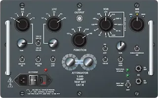 |
| Figure 9. An ILS test unit |
How does the ILS localizer provide horizontal guidance?
What is the difference between the localizer and the glideslope frequencies?
How do marker beacons indicate distance to the runway?
What role do Compass Locators play in an ILS approach?
RELATED POSTS