Much of aviation communication and navigation is accomplished through the use of radio waves. Communication by radio was the first use of radio frequency transmissions in aviation.
Radio Waves
A radio wave is invisible to the human eye. It is electromagnetic in nature and part of the electronic spectrum of wave activity that includes gamma rays, x-rays, ultraviolet rays, infrared waves, and visible light rays, as well as all radio waves. [Figure 1]
 |
| Figure 1. Radio waves are just some of the electromagnetic waves found in space |
The atmosphere is filled with these waves. Each wave occurs at a specific frequency and has a corresponding wavelength. The relationship between frequency and wavelength is inversely proportional. A high frequency wave has a short wavelength, and a low frequency wave has a long wavelength.
In aviation, a variety of radio waves are used for communication. Figure 2 illustrates the radio spectrum that includes the range of common aviation radio frequencies and their applications.
 |
| Figure 2. There is a wide range of radio frequencies. Only the very low frequencies and the extremely high frequencies are not used in aviation |
AC power of a particular frequency has a characteristic length of conductor that is resonant at that frequency. This length is the wavelength of the frequency that can be seen on an oscilloscope. Fractions of the wavelength also resonate, especially half of a wavelength, which is the same as half of the AC sine wave or cycle.
The frequency of an AC signal is the number of times the AC cycles every second. AC applied to the center of a radio antenna, a conductor half the wavelength of the AC frequency, travels the length of the antenna, collapses, and travels the length of the antenna in the opposite direction. The number of times it does this every second is known as the radio wave signal frequency or radio frequency (RF) as shown in Figure 2. As the current flows through the antenna, corresponding electromagnetic and electric fields build, collapse, build in the opposite direction, and collapse again. [Figure 3]
 |
| Figure 3. Radio waves are produced by applying an AC signal to an antenna. This creates a magnetic and electric field around the antenna. They build and collapse as the AC cycles. The speed at which the AC cycles does not allow the fields to completely collapse before the next fields build. The collapsing fields are then forced out into space as radio waves |
To transmit radio waves, an AC generator is placed at the midpoint of an antenna. As AC current builds and collapses in the antenna, a magnetic field also builds and collapses around it. An electric field also builds and subsides as the voltage shifts from one end of the antenna to the other. Both fields, the magnetic and the electric, fluctuate around the antenna at the same time. The antenna is half the wavelength of the AC signal received from the generator. At any one point along the antenna, voltage and current vary inversely to each other.
Because of the speed of the AC, the magnetic and electric fields created around the antenna do not have time to completely collapse as the AC cycles. Each new current flow creates new fields around the antenna that force the not-totally-collapsed fields from the previous AC cycle out into space. These are the radio waves. The process is continuous as long as AC is applied to the antenna. Thus, steady radio waves of a frequency determined by the input AC frequency propagate out into space.
Radio waves are directional and propagate out into space at 186,000 miles per second. The distance they travel depends on the frequency and the amplification of the signal AC sent to the antenna. The electric field component and the electromagnetic field component are oriented at 90° to each other, and at 90° to the direction that the wave is traveling. [Figure 4]
 |
| Figure 4. The electric field and the magnetic field of a radio wave are perpendicular to each other and to the direction of propagation of the wave |
Types of Radio Waves
Radio waves of different frequencies have unique characteristics as they propagate through the atmosphere. Very low frequency (VLF), LF, and medium frequency (MF) waves have relatively long wavelengths and utilize correspondingly long antennas. Radio waves produced at these frequencies ranging from 3 kHz to 3 MHz are known as ground waves or surface waves. This is because they follow the curvature of the earth as they travel from the broadcast antenna to the receiving antenna. Ground waves are particularly useful for long distance transmissions. Automatic direction finders (ADF) and LORAN navigational aids use these frequencies. [Figure 5]
 |
| Figure 5. Radio waves behave differently in the atmosphere depending in their frequency |
High frequency (HF) radio waves travel in a straight line and do not curve to follow the earth’s surface. This would limit transmissions from the broadcast antenna to receiving antennas only in the line-of-sight of the broadcast antenna except for a unique characteristic. HF radio waves reflect from the ionosphere layer of the atmosphere. This refraction extends the range of HF signals beyond line-of-sight. As a result, transoceanic aircraft often use HF radios for voice communication. The frequency range is between 2 to 25 MHz. These kinds of radio waves are known as sky waves. [Figure 5]
Above HF transmissions, radio waves are known as space waves. They are only capable of line-of-sight transmission and do not refract off of the ionosphere. [Figure 5] Most aviation communication and navigational aids operate with space waves. This includes VHF (30–300 MHz), UHF (300 MHz–3 GHz), and super high frequency (SHF) (3 GHz–30 GHz) radio waves.
VHF communication radios are the primary communication radios used in aviation. They operate in the frequency range from 118.0 MHz to 136.975 MHz. Seven hundred and twenty separate and distinct channels have been designated in this range with 25 kilohertz spacing between each channel. Further division of the bandwidth is possible, such as in Europe where 8.33 kilohertz separate each VHF communication channel. VHF radios are used for communications between aircraft and air traffic control (ATC), as well as air-to-air communication between aircraft. When using VHF, each party transmits and receives on the same channel. Only one party can transmit at any one time.
Loading Information onto a Radio Wave
The production and broadcast of radio waves does not convey any significant information. The basic radio wave discussed above is known as a carrier wave. To transmit and receive useful information, this wave is altered or modulated by an information signal. The information signal contains the unique voice or data information desired to be conveyed. The modulated carrier wave then carries the information from the transmitting radio to the receiving radio via their respective antennas. Two common methods of modulating carrier waves are amplitude modulation and frequency modulation.
Amplitude Modulation (AM)
A radio wave can be altered to carry useful information by modulating the amplitude of the wave. An audio-frequency signal, such as one produced by a microphone, is amplified and then superimposed over the AC carrier wave signal. As the varying audio-frequency information signal is amplified, the amplifier output current varies proportionally. The oscillator that creates the carrier wave does so with this varying current. The oscillator frequency output is consistent because it is built into the oscillator circuit. But the amplitude of the oscillator output varies in relation to the fluctuating current input. [Figure 6]
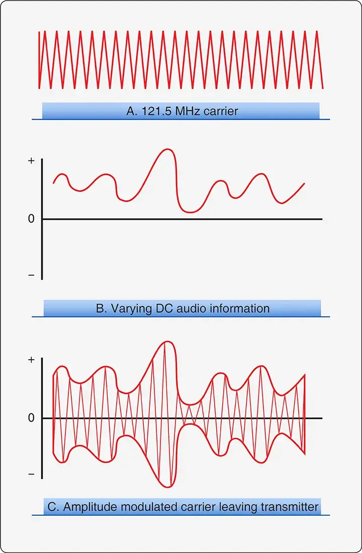 |
| Figure 6. A DC audio signal modifies the 121.5 MHz carrier wave as shown in C. The amplitude of the carrier wave (A) is changed in relation to modifier (B). This is known as amplitude modulation (AM) |
When the modulated carrier wave strikes the receiving antenna, voltage is generated that is the same as that which was applied to the transmitter antenna. However, the signal is weaker. It is amplified so that it can be demodulated. Demodulation is the process of removing the original information signal from the carrier wave. Electronic circuits containing capacitors, inductors, diodes, filters, etc., remove all but the desired information signal, which is identical to the original input signal. Then, the information signal is typically amplified again to drive speakers or other output devices. [Figure 7]
 |
| Figure 7. Demodulation of a received radio signal involves separating the carrier wave from the information signal |
AM has limited fidelity. Atmospheric noises or static alter the amplitude of a carrier wave making it difficult to separate the intended amplitude modulation caused by the information signal and that which is caused by static. It is used in aircraft VHF communication radios.
Frequency Modulation (FM)
Frequency modulation (FM) is widely considered superior to AM for carrying and deciphering information on radio waves. A carrier wave modulated by FM retains its constant amplitude. However, the information signal alters the frequency of the carrier wave in proportion to the strength of the signal. Thus, the signal is represented as slight variations in the normally consistent timing of the oscillations of the carrier wave. [Figure 8]
 |
| Figure 8. A frequency modulated (FM) carrier wave retains the consistent amplitude of the AC sign wave. It encodes the unique information signal with slight variations to the frequency of the carrier wave. These variations are shown as space variations between the peaks and valleys of the wave on an oscilloscope |
Since the transmitter oscillator output fluctuates during modulation to represent the information signal, FM bandwidth is greater than AM bandwidth. This is overshadowed by the ease with which noise and static can be removed from the FM signal. FM has a steady current flow and requires less power to produce since modulating an oscillator producing a carrier wave takes less power than modulating the amplitude of a signal using an amplifier.
Demodulation of an FM signal is similar to that of an AM receiver. The signal captured by the receiving antenna is usually amplified immediately since signal strength is lost as the wave travels through the atmosphere. Numerous circuits are used to isolate, stabilize, and remove the information from the carrier wave. The result is then amplified to drive the output device.
Single Side Band (SSB)
When two AC signals are mixed together, such as when a carrier wave is modulated by an information signal, three main frequencies result:
- Original carrier wave frequency;
- Carrier wave frequency plus the modulating frequency; and
- Carrier wave frequency minus the modulating frequency.
Due to the fluctuating nature of the information signal, the modulating frequency varies from the carrier wave up or down to the maximum amplitude of the modulating frequency during AM. These additional frequencies on either side of the carrier wave frequency are known as side bands. Each side band contains the unique information signal desired to be conveyed. The entire range of the lower and upper sidebands including the center carrier wave frequency is known as bandwidth. [Figure 9]
 |
| Figure 9. The bandwidth of an AM signal contains the carrier wave, the carrier wave plus the information signal frequencies, and the carrier wave minus the information signal frequencies |
There are a limited number of frequencies within the usable frequency ranges (i.e., LF, HF, and VHF). If different broadcasts are made on frequencies that are too close together, some of the broadcast from one frequency interfere with the adjacent broadcast due to overlapping side bands. The FCC divides the various frequency bands and issues rules for their use. Much of this allocation is to prevent interference. The spacing between broadcast frequencies is established so that a carrier wave can expand to include the upper and lower side bands and still not interfere with a signal on an adjacent frequency.
As use of the radio frequencies increases, more efficient allocation of bandwidth is imperative. Sending information via radio waves using the narrowest bandwidth possible is the focus of engineering moving forward. At the same time, fully representing all of the desired information or increasing the amount of information conveyed is also desired. Various methods are employed to keep bandwidth to a minimum, many of which restrict the quality or quantity of information able to be transmitted.
In lower frequency ranges, such as those used for ground wave and some sky wave broadcasts, SSB transmissions are a narrow bandwidth solution. Each side band represents the initial information signal in its entirety. Therefore, in an SSB broadcast, the carrier wave and either the upper or lower sidebands are filtered out. Only one sideband with its frequencies is broadcast since it contains all of the needed information. This cuts the bandwidth required in half and allows more efficient use of the radio spectrum. SSB transmissions also use less power to transmit the same amount of information over an equal distance. Many HF long-distance aviation communications are SSB. [Figure 10]
 |
| Figure 10. The additional frequencies above and below the carrier wave produced during modulation with the information signal are known as sidebands. Each sideband contains the unique information of the information signal and can be transmitted independent of the carrier wave and the other sideband |
Radio Transmitters and Receivers
Radio transmitters and receivers are electronic devices that manipulate electricity resulting in the transmission of useful information through the atmosphere or space.
Transmitters
A transmitter consists of a precise oscillating circuit or oscillator that creates an AC carrier wave frequency. This is combined with amplification circuits or amplifiers. The distance a carrier wave travels is directly related to the amplification of the signal sent to the antenna.
Other circuits are used in a transmitter to accept the input information signal and process it for loading onto the carrier wave. Modulator circuits modify the carrier wave with the processed information signal. Essentially, this is all there is to a radio transmitter.
A transmitter prepares and sends signals to an antenna that, in the process described above, radiates the waves out into the atmosphere. A transmitter with multiple channel (frequency) capability contains tuning circuitry that enables the user to select the frequency upon which to broadcast. This adjusts the oscillator output to the precise frequency desired. It is the oscillator frequency that is being tuned. [Figure 11]
 |
| Figure 11. Block diagram of a basic radio transmitter |
As shown in Figure 11, most radio transmitters generate a stable oscillating frequency and then use a frequency multiplier to raise the AC to the transmitting frequency. This allows oscillation to occur at frequencies that are controllable and within the physical working limits of the crystal in crystal-controlled oscillators.
Receivers
Antennas are simply conductors of lengths proportional to the wavelength of the oscillated frequency put out by the transmitter. An antenna captures the desired carrier wave as well as many other radio waves that are present in the atmosphere. A receiver is needed to isolate the desired carrier wave with its information. The receiver also has circuitry to separate the information signal from the carrier wave. It prepares it for output to a device, such as speakers or a display screen. The output is the information signal originally introduced into the transmitter.
A common receiver is the superheterodyne receiver. As with any receiver, it must amplify the desired radio frequency captured by the antenna since it is weak from traveling through the atmosphere. An oscillator in the receiver is used to compare and select the desired frequency out of all of the frequencies picked up by the antenna. The undesired frequencies are sent to ground.
A local oscillator in the receiver produces a frequency that is different than the radio frequency of the carrier wave. These two frequencies are mixed in the mixer. Four frequencies result from this mixing. They are the radio frequency, the local oscillator frequency, and the sum and difference of these two frequencies. The sum and difference frequencies contain the information signal.
The frequency that is the difference between the local oscillator frequency and the radio frequency carrier wave frequency is used during the remaining processing. In VHF aircraft communication radios, this frequency is 10.8 MHz. Called the intermediate frequency, it is amplified before it is sent to the detector. The detector, or demodulator, is where the information signal is separated from the carrier wave portion of the signal. In AM, since both sidebands contain the useful information, the signal is rectified leaving just one sideband with a weak version of the original transmitter input signal. In FM receivers, the varying frequency is changed to a varying amplitude signal at this point. Finally, amplification occurs for the output device. [Figure 12]
 |
| Figure 12. The basic stages used in a receiver to produce an output from a radio wave |
Over the years, with the development of transistors, microtransistors, and integrated circuits, radio transmitters and receivers have become smaller. Electronic bays were established on older aircraft as remote locations to mount radio devices simply because they would not fit in the flight deck. Today, many avionics devices are small enough to be mounted in the instrument panel, which is customary on most light aircraft. Because of the number of communication and navigation aids, as well as the need to present an uncluttered interface to the pilot, most complicated aircraft retain an area away from the flight deck for the mounting of avionics. The control heads of these units remain on the flight deck.
Transceivers
A transceiver is a communication radio that transmits and receives. The same frequency is used for both. When transmitting, the receiver does not function. The push to talk (PTT) switch blocks the receiving circuitry and allows the transmitter circuitry to be active. In a transceiver, some of the circuitry is shared by the transmitting and receiving functions of the device. So is the antenna. This saves space and the number of components used. Transceivers are half duplex systems where communication can occur in both directions but only one party can speak while the other must listen. VHF aircraft communication radios are usually transceivers. [Figure 13]
 |
| Figure 13. VHF aircraft communication transceivers |
Antennas
As stated, antennas are conductors that are used to transmit and receive radio frequency waves. Although the airframe technician has limited duties in relation to maintaining and repairing avionics, it is the responsibility of the technician to install, inspect, repair, and maintain aircraft radio antennas.
Three characteristics are of major concern when considering antennas:
- Length
- Polarization
- Directivity
The exact shape and material from which an antenna is made can alter its transmitting and receiving characteristics. Also note that some non-metallic aircraft have antennas embedded into the composite material as it is built up.
Length
When an AC signal is applied to an antenna, it has a certain frequency. There is a corresponding wavelength for that frequency. An antenna that is half the length of this wavelength is resonant. During each phase of the applied AC, all voltage and current values experience the full range of their variability. As a result, an antenna that is half the wavelength of the corresponding AC frequency is able to allow full voltage and full current flow for the positive phase of the AC signal in one direction. The negative phase of the full AC sine wave is accommodated by the voltage and current simply changing direction in the conductor. Thus, the applied AC frequency flows through its entire wavelength, first in one direction and then in the other. This produces the strongest signal to be radiated by the transmitting antenna. It also facilitates capture of the wave and maximum induced voltage in the receiving antenna. [Figure 14]
 |
| Figure 14. An antenna equal to the full length of the applied AC frequency wavelength would have the negative cycle current flow along the antenna as shown by the dotted line. An antenna that is ½ wavelength allows current to reverse its direction in the antenna during the negative cycle. This results in low current at the ends of the ½ wavelength antenna and high current in the center. As energy radiates into space, the field is strongest 90° to the antenna where the current flow is strongest |
Most radios, especially communication radios, use the same antenna for transmitting and receiving. Multichannel radios could use a different length antenna for each frequency, however, this is impractical. Acceptable performance can exist from a single antenna half the wavelength of a median frequency. This antenna can be made effectively shorter by placing a properly rated capacitor in series with the transmission line from the transmitter or receiver. This electrically shortens the resonant circuit of which the antenna is a part. An antenna may be electrically lengthened by adding an inductor in the circuit. Adjusting antenna length in this fashion allows the use of a single antenna for multiple frequencies in a narrow frequency range.
Many radios use a tuning circuit to adjust the effective length of the antenna to match the wavelength of the desired frequency. It contains a variable capacitor and an inductor connected in parallel in a circuit. Newer radios use a more efficient tuning circuit. It uses switches to combine frequencies from crystal controlled circuits to create a resonant frequency that matches the desired frequency. Either way, the physical antenna length is a compromise when using a multichannel communication or navigation device that must be electronically tuned for the best performance.
A formula can be used to find the ideal length of a half wavelength antenna required for a particular frequency as follows:
Antenna Length (feet) = 468 ÷ F MHz
The formula is derived from the speed of propagation of radio waves, which is approximately 300 million meters per second. It takes into account the dielectric effect of the air at the end of an antenna that effectively shortens the length of the conductor required.
VHF radio frequencies used by aircraft communication radios are 118–136.975 MHz. The corresponding half wavelengths of these frequencies are 3.96 – 3.44 feet (47.5–41.2 inches). Therefore, VHF antennas are relatively long. Antennas one-quarter of the wavelength of the transmitted frequency are often used. This is possible because when mounted on a metal fuselage, a ground plane is formed and the fuselage acts as the missing one-quarter length of the half wavelength antenna. This is further discussed in the following antenna types section.
Polarization, Directivity, and Field Pattern
Antennas are polarized. They radiate and receive in certain patterns and directions. The electric field caused by the voltage in the conductor is parallel to the polarization of an antenna. It is caused by the voltage difference between each end of the antenna. The electromagnetic field component of the radio wave is at 90° to the polarization. It is caused by changing current flow in the antenna. These fields were illustrated in Figure 3 and 4.
As radio waves radiate out from the antenna they propagate in a specific direction and in a specific pattern. This is the antenna field. The orientation of the electric and electromagnetic fields remains at 90° to each other but radiate from the antenna with varying strength in different directions. The strength of the radiated field varies depending on the type of antenna and the angular proximity to it. All antennas, even those that are omnidirectional, radiate a stronger signal in some direction compared to other directions. This is known as the antenna field directivity.
Receiving antennas with the same polarization as the transmitting antenna generate the strongest signal. A vertically polarized antenna is mounted up and down. It radiates waves out from it in all directions. To receive the strongest signal from these waves, the receiving antenna should also be positioned vertically so the electromagnetic component of the radio wave can cross it at as close to a 90° angle as possible for most of the possible proximities. [Figure 15]
 |
| Figure 15. A vertically polarized antenna radiates radio waves in a donut-like pattern in all directions |
Horizontally polarized antennas are mounted side to side (horizontally). They radiate in a donut-like field. The strongest signals come from, or are received at, 90° to the length of the antenna. There is minimal radiation off the ends of the antenna. Figure 16 illustrates the field produced by a horizontally polarized antenna.
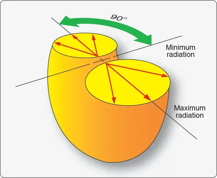 |
| Figure 16. A horizontally polarized antenna radiates in a donut-like pattern. The strongest signal is at 90° to the length of the conductor |
Many vertical and horizontal antennas on aircraft are mounted at a slight angle off the plane of the aircraft. This allows the antenna to receive a weak signal rather than no signal at all when the polarization of the receiving antenna is not identical to the transmitting antenna. [Figure 17]
 |
| Figure 17. Many antenna are canted for better reception |
Antenna Types
There are three basic types of antennas used in aviation:
- Dipole antenna
- Marconi antenna
- Loop antenna
Dipole Antenna
The dipole antenna is the type of antenna referred to in the discussion of how a radio wave is produced. It is a conductor, the length of which is approximately equal to half the wavelength of the transmission frequency. This sometimes is referred to as a Hertz antenna. The AC transmission current is fed to a dipole antenna in the center. As the current alternates, current flow is greatest in the middle of the antenna and gradually less as it approaches the ends. Then, it changes direction and flows the other way. The result is that the largest electromagnetic field is in the middle of the antenna and the strongest radio wave field is perpendicular to the length of the antenna. Most dipole antennas in aviation are horizontally polarized.
A common dipole antenna is the V-shaped VHF navigation antenna, known as a VOR antenna, found on numerous aircraft. Each arm of the V is one-fourth wavelength creating a half wave antenna which is fed in the center. This antenna is horizontally polarized. For a dipole receiving antenna, this means it is most sensitive to signals approaching the antenna from the sides rather than head-on in the direction of flight. [Figure 18]
 |
| Figure 18. The V-shaped VOR navigation antenna is a common dipole antenna |
Marconi Antenna
A Marconi antenna is a one-fourth wave antenna. It achieves the efficiency of a half wave antenna by using the mounting surface of the conductive aircraft skin to create the second one-fourth wavelength. Most aircraft VHF communications antennas are Marconi antennas. They are vertically polarized and create a field that is omnidirectional. On fabric skinned aircraft, the ground plane that makes up the second one-fourth wavelength of the antenna must be fashioned under the skin where the Marconi antenna is mounted. This can be done with thin aluminum or aluminum foil. Sometimes four or more wires are extended under the skin from the base of the vertical antenna that serve as the ground plane. This is enough to give the antenna the proper conductive length. The same practice is also utilized on ground-based antennas. [Figure 19]
 |
| Figure 19. On a metal-skinned aircraft, a ¼ wavelength Marconi antenna is used. The skin is the ground plane that creates the 2nd quarter of the antenna required for resonance (left). On a nonmetallic-skinned aircraft, wires, conductive plates or strips equal in length to the antenna must be installed under the skin to create the ground plane (right) |
Loop Antenna
The third type of antenna commonly found on aircraft is the loop antenna. When the length of an antenna conductor is fashioned into a loop, its field characteristics are altered significantly from that of a straight half-wavelength antenna. It also makes the antenna more compact and less prone to damage.
Used as a receiving antenna, the loop antenna’s properties are highly direction-sensitive. A radio wave intercepting the loop directly broadside causes equal current flow in both sides of the loop. However, the polarity of the current flows is opposite each other. This causes them to cancel out and produce no signal. When a radio wave strikes the loop antenna in line with the plane of the loop, current is generated first in one side, and then in the other side. This causes the currents to be out of phase and the strongest signal can be generated from this angle. The phase difference (and strength) of the generated current varies proportionally to the angle at which the radio wave strikes the antenna loop. This characteristic is useful and is discussed further in the section on automatic direction finder (ADF) navigational aids. [Figure 20]
 |
| Figure 20. A loop antenna is highly direction-sensitive. A signal origin perpendicular or broadside to the loop creates a weak signal (A). A signal origin parallel or in the plain of the loop creates a strong signal (B) |
Transmission Lines
Transmitters and receivers must be connected to their antenna(s) via conductive wire. These transmission lines are coaxial cables, also known as coax. Coax consists of a center wire conductor surrounded by a semirigid insulator. Surrounding the wire and insulator material is a conductive, braided cover that runs the length of the cable. Finally, a waterproof covering is set around the braided shield to protect the entire assembly from the elements. The braided cover in the coax shields the inner conductor from any external fields. It also prevents the fields generated by the internal conductor from radiating. For optimum performance, the impedance of the transmission line should be equal to the impedance of the antenna. In aviation antenna applications, this is often approximately 50 ohms. [Figure 21]
 |
| Figure 21. Coaxial cable is used as the transmission line between an antenna and its transmitters and/or receiver |
Special connectors are used for coaxial cable. A variety can be seen in Advisory Circular (AC) 43.13-1b, Chapter 11, Section 17, Figure 11-37. The technician should follow all manufacturer’s instructions when installing transmission lines and antennas. Correct installation is critical to radio and antenna performance.
What is the relationship between frequency and wavelength in radio waves?
What are the differences between ground, sky, and space waves?
Why is the Marconi antenna commonly used on metal-skinned aircraft?
How does frequency modulation (FM) differ from amplitude modulation (AM)?
RELATED POSTS