
Resistance
As mentioned, resistance creates an opposition to current in an AC circuit similar to the resistance of a DC circuit. The current through a resistive portion of an AC circuit is inversely proportional to the resistance and directly proportional to the voltage applied to that circuit or portion of the circuit. The equations I = E / R & E = I × R show how current is related to both voltage and resistance. It should be noted that resistance in an AC circuit does not create a phase shift between voltage and current. Figure 1 shows how a circuit of 10 ohms allows 11.5 amps of current flow through an AC resistive circuit of 115 volts. |
| Figure 1. Resistance |
I = E
R
I = 115V
10Ω
I = 11.5 amps
Inductive Reactance
When moving a magnet through a coil of wire, a voltage is induced across the coil. If a complete circuit is provided, then a current will also be induced. The amount of induced voltage is directly proportional to the rate of change of the magnetic field with respect to the coil. Conversely, current flowing through a coil of wire produces a magnetic field. When this wire is formed into a coil, it then becomes a basic inductor.The primary effect of a coil is its property to oppose any change in current through it. This property is called inductance. When current flows through any conductor, a magnetic field starts to expand from the center of the wire. As the lines of magnetic force grow outward through the conductor, they induce an EMF in the conductor itself. The induced voltage is always in the direction opposite to the direction of the applied current flow. The effects of this countering EMF are to oppose the applied current. This effect is only a temporary condition. Once the current reaches a steady value in the conductor, the lines of magnetic force are no longer expanding and the countering EMF is no longer present. Since AC is constantly changing in value, the inductance repeats in a cycle always opposite the applied voltage. It should be noted that the unit of measure for inductance is the henry (H).
The physical factors that affect inductance are:
- Number of turns—doubling the number of turns in a coil produces a field twice as strong if the same current is used. As a general rule, the inductance varies with the square of the number of turns.
- Cross-sectional area of the coil—the inductance of a coil increases directly as the cross-sectional area of the core increases. Doubling the radius of a coil increases the inductance by a factor of four.
- Length of a coil—doubling the length of a coil, while keeping the same number of turns, reduces inductance by one-half.
- Core material around which the coil is formed—coils are wound on either magnetic or nonmagnetic materials. Some nonmagnetic materials include air, copper, plastic, and glass. Magnetic materials include nickel, iron, steel, and cobalt, which have a permeability that provides a better path for the magnetic lines of force and permit a stronger magnetic field.
Since AC is in a constant state of change, the magnetic fields within an inductor are also continuously changing and create an inducted voltage/current. This induced voltage opposes the applied voltage and is known as the counter EMF. This opposition is called inductive reactance, symbolized by XL, and is measured in ohms. This characteristic of the inductor may also create a phase shift between voltage and current of the circuit. The phase shift created by inductive reactance always causes voltage to lead current. That is, the voltage of an inductive circuit reaches its peak values before the current reaches peak values.
Inductance is the property of a circuit to oppose any change in current and is measured in henries. Inductive reactance is a measure of how much the countering EMF in the circuit opposes the applied current. The inductive reactance of a component is directly proportional to the inductance of the component and the applied frequency to the circuit. By increasing either the inductance or applied frequency, the inductive reactance likewise increases and presents more opposition to current in the circuit. This relationship is given as XL = 2πfL Where XL = inductive reactance in ohms, L = inductance in henries, f = frequency in cycles per second, and π = 3.1416.
In Figure 2, an AC series circuit is shown in which the inductance is 0.146 henry and the voltage is 110 volts at a frequency of 60 cycles per second. Inductive reactance is determined by the following method.
 |
| Figure 2. AC circuit containing inductance |
XL = 2π × f × L
XL = 6.28 × 60 × 0.146
XL = 55Ω
In AC series circuits, inductive reactance is added like resistances in series in a DC circuit. [Figure 3] The total reactance in the illustrated circuit equals the sum of the individual reactances.
 |
| Figure 3. Inductances in series |
XL = XL1 + XL2
XL =10Ω + 15Ω
XLT = 25Ω
The total reactance of inductors connected in parallel is found the same way as the total resistance in a parallel circuit. [Figure 4] Thus, the total reactance of inductances connected in parallel, as shown, is expressed as:

 |
| Figure 4. Inductances in parallel |
Capacitive Reactance
Capacitance is the ability of a body to hold an electric charge. In general, a capacitor is constructed of two parallel plates separated by an insulator. The insulator is commonly called the dielectric. The capacitor’s plates have the ability to store electrons when charged by a voltage source. The capacitor discharges when the applied voltage is no longer present and the capacitor is connected to a current path. In an electrical circuit, a capacitor serves as a reservoir or storehouse for electricity.The basic unit of capacitance is the farad and is given by the letter F. By definition, one farad is one coulomb of charge stored with one volt across the plates of the capacitor. In practical terms, one farad is a large amount of capacitance. Typically, in electronics, much smaller units are used. The two more common smaller units are the microfarad (μF), which is 10-6 farad and the picofarad (pF), which is 10-12 farad.
Capacitance is a function of the physical properties of the capacitor:
- The capacitance of parallel plates is directly proportional to their area. A larger plate area produces a larger capacitance, and a smaller area produces less capacitance. If we double the area of the plates, there is room for twice as much charge.
- The capacitance of parallel plates is inversely proportional to the distance between the plates.
- The dielectric material effects the capacitance of parallel plates. The dielectric constant of a vacuum is defined as 1, and that of air is very close to 1. These values are used as a reference, and all other materials have values relative to that of air (vacuum).
When an AC is applied in the circuit, the charge on the plates constantly changes. [Figure 5] This means that electricity must flow first from Y clockwise around to X, then from X counterclockwise around to Y, then from Y clockwise around to X, and so on. Although no current flows through the insulator between the plates of the capacitor, it constantly flows in the remainder of the circuit between X and Y. As this current alternates to and from the capacitor, a certain time lag is created. When a capacitor charges or discharges through a resistance, a certain amount of time is required for a full charge or discharge. The voltage across the capacitor does not change instantaneously. The rate of charging or discharging is determined by the time constant of the circuit. This rate of charge and discharge creates an opposition to current flow in AC circuits known as capacitive reactance. Capacitive reactance is symbolized by XC and is measured in ohms. This characteristic of a capacitor may also create a phase shift between voltage and current of the circuit. The phase shift created by capacitive reactance always causes current to lead voltage. That is, the current of a capacitive circuit reaches its peak values before the voltage reaches peak values.
 |
| Figure 5. Capacitor in an AC circuit |
Capacitive reactance is a measure of how much the capacitive circuit opposes the applied current flow. Capacitive reactance is measured in ohms. The capacitive reactance of a circuit is indirectly proportional to the capacitance of the circuit and the applied frequency to the circuit. By increasing either the capacitance or applied frequency, the capacitive reactance decreases, and vice versa. This relationship is given as:
XC = 1
2πfC
2πfC
Where: XC = capacitive reactance in ohms, C = capacitance in farads, f = frequency in cycles per second, and π = 3.1416.
In Figure 5, a series circuit is shown in which the applied voltage is 110 volts at 400 cps, and the capacitance of a condenser is 80 mf. Find the capacitive reactance and the current flow.
To find the capacitive reactance, the following equation:
XC = 1
2πfC
First, the capacitance, 80 μf, is changed to farads by dividing 80 by 1,000,000, since 1 million microfarads is equal to 1 farad. This quotient equals 0.000080 farad. This is substituted in the equation:
XC = 1
2πfC
XC = 1 2πfC
2π(400)(0.000080)
XC = 4.97Ω
[ad-mid]
Impedance
The total opposition to current flow in an AC circuit is known as impedance and is represented by the letter Z. The combined effects of resistance, inductive reactance, and capacitive reactance make up impedance (the total opposition to current flow in an AC circuit). In order to accurately calculate voltage and current in AC circuits, the effect of inductance and capacitance along with resistance must be considered. Impedance is measured in ohms.The rules and equations for DC circuits apply to AC circuits only when that circuit contains resistance alone and no inductance or capacitance. In both series and parallel circuits, if an AC circuit consists of resistance only, the value of the impedance is the same as the resistance, and Ohm’s law for an AC circuit, I = E/Z, is exactly the same as for a DC circuit. Figure 6 illustrates a series circuit containing a heater element with 11 ohms resistance connected across a 110-volt source. To find how much current flows if 110 volts AC is applied, the following example is solved:
I = E
Z
I = 110V
11Ω
I = 10 amps
Z
I = 110V
11Ω
I = 10 amps
 = Resistance (R)") |
| Figure 6. Ohm's Law applies to AC circuit only when circuit consists of resistance only. Impedance (Z) = Resistance (R) |
 |
| Figure 7. Two resistance values in parallel connected to an AC voltage. Impedance is equal to the total resistance of the circuit |
Once again, the calculations would be handled the same as if it were a DC circuit and the following would apply:

Since this is a pure resistive circuit RT = Z (Resistance = Impedance)
ZT = RT
ZT = 10Ω
ZT = 10Ω
To determine the current flow in the circuit use the equation:
I = E
Z
I = 50V
10Ω
I = 5 amps
I = E
Z
I = 50V
10Ω
I = 5 amps
Impedance is the total opposition to current flow in an AC circuit. If a circuit has inductance or capacitance, one must take into consideration resistance (R), inductive reactance (XL), and/or capacitive reactance (XC) to determine impedance (Z). In this case, Z does not equal RT. Resistance and reactance (inductive or capacitive) cannot be added directly, but they can be considered as two forces acting at right angles to each other. Thus, the relation between resistance, reactance, and impedance may be illustrated by a right triangle. [Figure 8] Since these quantities may be related to the sides of a right triangle, the formula for finding the impedance can be found using the Pythagorean Theorem. It states that the square of the hypotenuse is equal to the sum of the squares of the other two sides. Thus, the value of any side of a right triangle can be found if the other two sides are known.
 |
| Figure 8. Impedance triangle |
In practical terms, if a series AC circuit contains resistance and inductance, as shown in Figure 9, the relation between the sides can be stated as:
 |
| Figure 9. A circuit containing resistance and inductance |
This formula can be used to determine the impedance when the values of inductive reactance and resistance are known. It can be modified to solve for impedance in circuits containing capacitive reactance and resistance by substituting XC in the formula in place of XL. In circuits containing resistance with both inductive and capacitive reactance, the reactances can be combined; but because their effects in the circuit are exactly opposite, they are combined by subtraction (the smaller number is always subtracted from the larger):
or
X = XC – XL
Figure 9 shows example 1. Here, a series circuit containing a resistor and an inductor are connected to a source of 110 volts at 60 cycles per second. The resistive element is a simple measuring 6 ohms, and the inductive element is a coil with an inductance of 0.021 henry. What is the value of the impedance and the current through the circuit?
Solution:
First, the inductive reactance of the coil is computed:
XL = 2π × f × L
XL = 6.28 × 60 × 0.021
XL = 8 ohms inductive reactance
Next, the total impedance is computed:

Remember when making calculations for Z always use inductive reactance not inductance, and use capacitive reactance, not capacitance.
Once impedance is found, the total current can be calculated.
Since this circuit is resistive and inductive, there is a phase shift where voltage leads current.
Example 2 is a series circuit illustrated in which a capacitor of 200 μf is connected in series with a 10 ohm resistor. [Figure 10] What is the value of the impedance, the current flow, and the voltage drop across the resistor?
I = E
Z
I = 110V
10Ω
I = 11 amps
Z
I = 110V
10Ω
I = 11 amps
Since this circuit is resistive and inductive, there is a phase shift where voltage leads current.
Example 2 is a series circuit illustrated in which a capacitor of 200 μf is connected in series with a 10 ohm resistor. [Figure 10] What is the value of the impedance, the current flow, and the voltage drop across the resistor?
 |
| Figure 10. A circuit containing resistance and capacitance |
Solution:
First, the capacitance is changed from microfarads to farads. Since 1 million microfarads equal 1 farad, then 200 μf = 0.000200 farads.
Next solve for capacitive reactance:
First, the capacitance is changed from microfarads to farads. Since 1 million microfarads equal 1 farad, then 200 μf = 0.000200 farads.
Next solve for capacitive reactance:


Since this circuit is resistive and capacitive, there is a phase shift where current leads voltage:
To find the current:
IT = E
ZIT = 110V
6.4Ω
IT = 6.7 amps
To find the voltage drop across the resistor (ER):
ER = I × R
ER = 6.7A × 10Ω
ER = 67 volts
ER = 6.7A × 10Ω
ER = 67 volts
To find the voltage drop over the capacitor (EC):
EC = I × XC
EC = 6.7A × 13Ω
EC = 86.1 volts
The sum of these two voltages does not equal the applied voltage, since the current leads the voltage. Use the following formula to find the applied voltage:


Solution:
EC = I × XC
EC = 6.7A × 13Ω
EC = 86.1 volts
The sum of these two voltages does not equal the applied voltage, since the current leads the voltage. Use the following formula to find the applied voltage:

When the circuit contains resistance, inductance, and capacitance, the following equation is used to find the impedance.
Example 3: What is the impedance of a series circuit consisting of a capacitor with a capacitive reactance of 7 ohms, an inductor with an inductive reactance of 10 ohms, and a resistor with a resistance of 4 ohms? [Figure 11]
 |
| Figure 11. A circuit containing resistance, inductance, and capacitance |
Solution:
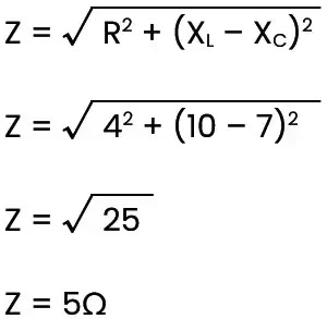

Remember that inductive and capacitive reactances can cause a phase shift between voltage and current. In this example, inductive reactance is larger than capacitive reactance, so the voltage leads current.
It should be noted that since inductive reactance, capacitive reactance, and resistance affect each other at right angles, the voltage drops of any series AC circuit should be added using vector addition. Figure 12 shows the voltage drops over the series AC circuit described in example 3 above.
 |
| Figure 12. Voltage drops |
To calculate the individual voltage drops, simply use the equations:
EXL = I × XL
EXC = I × XC
To determine the total applied voltage for the circuit, each individual voltage drop must be added using vector addition.

Parallel AC Circuits
When solving parallel AC circuits, one must also use a derivative of the Pythagorean Theorem. The equation for finding impedance in an AC circuit is as follows:
To determine the total impedance of the parallel circuit shown in Figure 13, one would first determine the capacitive and inductive reactances. (Remember to convert microfarads to farads.)
 |
| Figure 13. Total impedance of parallel circuit |

Next, the impedance can be found:


To determine the current flow through each parallel path of the circuit, calculate IR, IL, and IC.

It should be noted that the total current flow of parallel circuits is found by using vector addition of the individual current flows as follows:
