Electrical power in aircraft is primarily generated through electromagnetic induction. Understanding this principle is essential for analyzing generators, alternators, and electrical system performance.
Electrical energy can be produced through a number of methods. Common methods include the use of light, pressure, heat, chemical, and electromagnetic induction. Of these processes, electromagnetic induction is most responsible for the generation of the majority of the electrical power used by humans. Virtually all mechanical devices (generators and alternators) that produce electrical power employ the process of electromagnetic induction. The use of light, pressure, heat, and chemical sources for electrical power is found on aircraft but produce a minimal amount of all the electrical power consumed during a typical flight.
In brief, light can produce electricity using a solar cell (photovoltaic cell). These cells contain a certain chemical that converts light energy into voltage/current.
Using pressure to generate electrical power is commonly known as the piezoelectric effect. The piezoelectric effect (piezo or piez taken from Greek: to press; pressure; to squeeze) is a result of the application of mechanical pressure on a dielectric or nonconducting crystal.
Chemical energy can be converted into electricity, most commonly in the form of a battery. A primary battery produces electricity using two different metals in a chemical solution such as an alkaline electrolyte. A chemical reaction exists between the metals which frees more electrons in one metal than in the other.
Heat used to produce electricity creates the thermoelectric effect. When a device called a thermocouple is subjected to heat, a voltage is produced. A thermocouple is a junction between two different metals that produces a voltage related to a temperature difference. If the thermocouple is connected to a complete circuit, a current also flows. Thermocouples are often found on aircraft as part of a temperature monitoring system, such as a cylinder head temperature gauge.
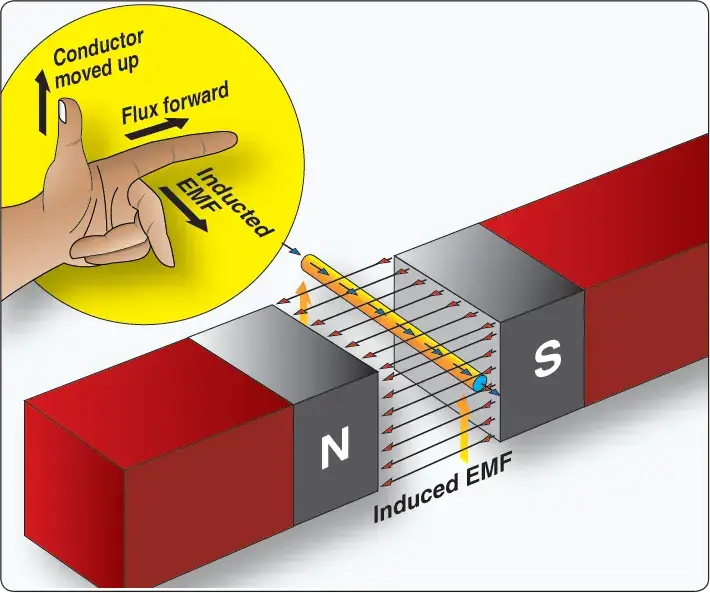
Electromagnetic induction is the process of producing a voltage (EMF) by moving a magnetic field in relation to a conductor. As shown in Figure 1, when a conductor (wire) is moved through a magnetic field, an EMF is produced in the conductor. If a complete circuit is connected to the conductor, the voltage produces current flow.
 |
| Figure 1. Inducing an EMF in a conductor |
One single conductor does not produce significant voltage/current via electromagnetic induction. [Figure 1] In practice, instead of a single wire, a coil of wire is moved through the magnetic field of a strong magnet. This produces a greater electrical output. In many cases, the magnetic field is created by using a powerful electromagnet. This allows for the production of a greater voltage/current due to the stronger magnetic field produced by the electromagnet when compared to an ordinary magnet.
Please note that this text often refers to voltage/current with regard to electrical power. Remember voltage (electrical pressure) must be present to produce a current (electron flow). Hence, the output energy generated through the process of electromagnetic induction always consists of voltage.
Current also results when a complete circuit is connected to that voltage. Electrical power is produced when there is both electrical pressure E (EMF) and current (I). Power = Current × Voltage (P = I × E)
It is the relative motion between a conductor and a magnetic field that causes current to flow in the conductor. Either the conductor or magnet can be moving or stationary. When a magnet and its field are moved through a coiled conductor, as shown in Figure 2, a DC voltage with a specific polarity is produced. The polarity of this voltage depends on the direction in which the magnet is moved and the position of the north and south poles of the magnetic field. The generator left-hand rule can be used to determine the direction of current flow within the conductor. [Figure 3] Of course, the direction of current flow is a function of the polarity of the voltage induced into the conductor.
 |
| Figure 2. Inducing a current flow |
 |
| Figure 3. An application of the generator left-hand rule |
In practice, producing voltage/current using the process of electromagnetic induction requires a rotating machine. In general, on aircraft, a generator or alternator employs the principles of electromagnetic induction to create electrical power for the aircraft. Either the magnetic field can rotate or the conductor can rotate. [Figure 4] The rotating component is driven by a mechanical device, such as an aircraft engine.
 |
| Figure 4. Voltage induced in a loop |
During the process of electromagnetic induction, the value of the induced voltage/current depends on three basic factors:
- Number of turns in the conductor coil (more loops equals greater induced voltage)
- Strength of the electromagnet (the stronger the magnetic field, the greater the induced voltage)
- Speed of rotation of the conductor or magnet (the faster the rotation, the greater the induced voltage)
Figure 5 illustrates the basics of a rotating machine used to produce voltage. The simple generating device consists of a rotating loop, marked A and B, placed between two magnetic poles, N and S. The ends of the loop are connected to two metal slip rings (collector rings), C1 and C2. Current is taken from the collector rings by brushes. If the loop is considered as separate wires, A and B, and the left-hand rule for generators is applied, then it can be observed that as wire B moves up across the field, a voltage is induced that causes the current to flow towards the reader. As wire A moves down across the field, a voltage is induced that causes the current to flow away from the reader. When the wires are formed into a loop, the voltages induced in the two sides of the loop are combined. Therefore, for explanatory purposes, the action of either conductor, A or B, while rotating in the magnetic field is similar to the action of the loop.
 |
| Figure 5. Simple generator |
Figure 6 illustrates the generation of alternating current (AC) with a simple loop conductor rotating in a magnetic field. As it is rotated in a counterclockwise direction, varying voltages are induced in the conductive loop.
 |
| Figure 6. Generation of a sine wave |
Position 1
The conductor A moves parallel to the lines of force. Since it cuts no lines of force, the induced voltage is zero. As the conductor advances from position 1 to position 2, the induced voltage gradually increases.
Position 2
The conductor is now moving in a direction perpendicular to the flux and cuts a maximum number of lines of force; therefore, a maximum voltage is induced. As the conductor moves beyond position 2, it cuts a decreasing amount of flux, and the induced voltage decreases.
Position 3
At this point, the conductor has made half a revolution and again moves parallel to the lines of force, and no voltage is induced in the conductor. As the A conductor passes position 3, the direction of induced voltage now reverses since the A conductor is moving downward, cutting flux in the opposite direction. As the A conductor moves across the south pole, the induced voltage gradually increases in a negative direction until it reaches position 4.
Position 4
Like position 2, the conductor is again moving perpendicular to the flux and generates a maximum negative voltage. From position 4 to position 5, the induced voltage gradually decreases until the voltage is zero, and the conductor and wave are ready to start another cycle.
Position 5
The curve shown at position 5 is called a sine wave. It represents the polarity and the magnitude of the instantaneous values of the voltages generated. The horizontal baseline is divided into degrees (or time) and the vertical distance above or below the baseline represents the value of voltage at each particular point in the rotation of the loop.
What is electromagnetic induction in simple terms?
What three factors determine the amount of voltage induced?
Why does a rotating loop produce alternating current (AC) naturally?
What is the "Generator Left-Hand Rule"?
RELATED POSTS