Understanding the relationship between voltage, current, and resistance is fundamental to aircraft electrical systems. These basic electrical principles allow technicians to analyze circuits, diagnose faults, and ensure proper system operation.
Ohm's Law
Ohm’s Law describes the basic mathematical relationships of electricity. The law was named after German physicist George Simon Ohm (1789–1854). Ohm’s Law states that the electron flow (current) through a conductor is directly proportional to the voltage (electrical pressure) applied to that conductor and inversely proportional to the resistance of the conductor. The unit used to measure resistance is called the ohm.
The symbol for the ohm is the Greek letter omega (Ω). In mathematical formulas, the capital letter R refers to resistance. The resistance of a conductor and the voltage applied to it determine the number of amperes of current flowing through the conductor. Thus, 1 ohm of resistance limits the current flow to 1 ampere in a conductor to which a voltage of 1 volt is applied. The primary formula derived from Ohm’s Law is: E = I × R (E = electromotive force measured in volts, I = current flow measured in amps, and R = resistance measured in ohms). This formula can also be written to solve for current or resistance:
E = I × R
I = E / R
R = E / I
Ohm’s Law provides a foundation of mathematical formulas that predict how electricity responds to certain conditions. [Figure 1] For example, Ohm’s Law can be used to calculate that a lamp of 12 ohms (Ω) passes a current of 2 amps when connected to a 24-volt direct current (DC) power source.
 |
| Figure 1. Ohm's Law used to calculate how much current a lamp will pass when connected to a 24-volt DC power source |
Example 1
A 28-volt landing light circuit has a lamp with 4 ohms of resistance. Calculate the total current of the circuit.
I = E / R
I = 28 volts / 4Ω
I = 7 amps
Example 2
A 28-volt deice boot circuit has a current of 6.5 amps. Calculate the resistance of the deice boot.
R = E / I
I = 28 volts / 6.5 amps
R = 4.31Ω
Example 3
A taxi light has a resistance of 4.9 Ω and a total current of 2.85 amps. Calculate the system voltage.
E = I × R
E = 2.85 × 4.9Ω
E = 14 volts
Whenever troubleshooting aircraft electrical circuits, it is always valuable to consider Ohm’s Law. A good understanding of the relationship between resistance and current flow can help one determine if a circuit contains an open or a short. Remembering that a low resistance means increased current can help explain why circuit breakers pop or fuses blow. In almost all cases, aircraft loads are wired in parallel to each other; therefore, there is a constant voltage supplied to all loads and the current flow through a load is a function of that load’s resistance.
Figure 2 illustrates several ways of using Ohm’s Law for the calculation of current, voltage, and resistance.
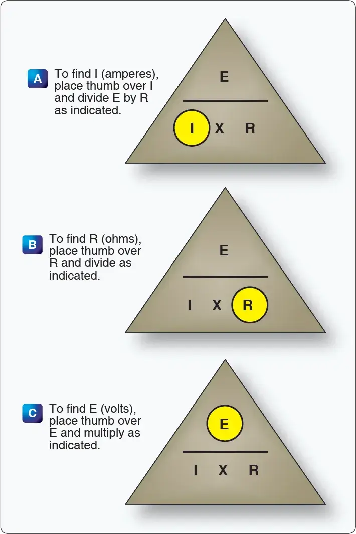 |
| Figure 2. Ohm's Law chart |
Current
Electrical current is the movement of electrons. This electron movement is referred to as current, flow, or current flow. In practical terms, this movement of electrons must take place within a conductor (wire). Current is typically measured in amps. The symbol for current is I and the symbol for amperes is A.
The current flow is actually the movement of the free electrons found within conductors. Common conductors include copper, silver, aluminum, and gold. The term “free electron” describes a condition in some atoms where the outer electrons are loosely bound to their parent atom. These loosely bound electrons are easily motivated to move in a given direction when an external source, such as a battery, is applied to the circuit. These electrons are attracted to the positive terminal of the battery, while the negative terminal is the source of the electrons. So, the measure of current is actually the number of electrons moving through a conductor in a given amount of time.
The internationally accepted unit for current is the ampere (A). One ampere (A) of current is equivalent to 1 coulomb (C) of charge passing through a conductor in 1 second. One coulomb of charge equals 6.28 × 10¹⁸ electrons. Obviously, the unit of amperes is a much more convenient term to use than coulombs. The unit of coulombs is simply too small to be practical.
When current flow is in one direction, it is called direct current (DC). Later in the text, the form of current that periodically oscillates back and forth within the circuit is discussed. The present discussion is concerned only with the use of DC. It should be noted that as with the movement of any mass, electron movement (current flow) only occurs when there is a force present to push the electrons. This force is commonly called voltage (described in more detail in the next section). When a voltage is applied across the conductor, an electromotive force creates an electric field within the conductor, and a current is established. The electrons do not move in a straight direction, but undergo repeated collisions with other nearby atoms within a conductor. These collisions usually knock other free electrons from their atoms, and these electrons move on toward the positive end of the conductor with an average velocity called the drift velocity, which is relatively low speed. To understand the nearly instantaneous speed of the effect of the current, it is helpful to visualize a long tube filled with steel balls. [Figure 3]
 |
| Figure 3. Electron flow image |
It can be seen that a ball introduced in one end of the tube, which represents the conductor, immediately causes a ball to be emitted at the opposite end of the tube. Thus, electric current can be viewed as instantaneous, even though it is the result of a relatively slow drift of electrons.
Conventional Current Theory and Electron Theory
There are two competing schools of thought regarding the flow of electricity. The two explanations are the conventional current theory and the electron theory. Both theories describe the movement of electrons through a conductor. They simply explain the direction current moves. Typically during troubleshooting or the connection of electrical circuits, the use of either theory can be applied as long as it is used consistently. The Federal Aviation Administration (FAA) officially defines current flow using electron theory (negative to positive).
The conventional current theory was initially advanced by Benjamin Franklin, who reasoned that current flowed out of a positive source into a negative source or an area that lacked an abundance of charge. The notation assigned to the electric charges was positive (+) for the abundance of charge and negative (−) for a lack of charge. It then seemed natural to visualize the flow of current as being from the positive (+) to the negative (−). Later discoveries were made that proved that just the opposite is true. Electron theory describes what actually happens in the case of an abundance of electrons flowing out of the negative (−) source to an area that lacks electrons or the positive (+) source. Both conventional flow and electron flow are used in industry.
Electromotive Force (Voltage)
Voltage is most easily described as electrical pressure force. It is the electromotive force (EMF), or the push or pressure from one end of the conductor to the other, that ultimately moves the electrons. The symbol for EMF is the capital letter E. EMF is always measured between two points and voltage is considered a value between two points. For example, across the terminals of the typical aircraft battery, voltage can be measured as the potential difference of 12 volts or 24 volts. That is to say that between the two terminal posts of the battery, there is a voltage available to push current through a circuit. Free electrons in the negative terminal of the battery move toward the excessive number of positive charges in the positive terminal. The net result is a flow or current through a conductor. There cannot be a flow in a conductor unless there is an applied voltage from a battery, generator, or ground power unit. The potential difference, or the voltage across any two points in an electrical system, can be determined by:
V₁ − V₂ = V_drop
Example
The voltage at one point is 14 volts. The voltage at a second point in the circuit is 12.1 volts. To calculate the voltage drop, use the formula above to get a total voltage drop of 1.9 volts.
Figure 4 illustrates the flow of electrons of electric current. Two interconnected water tanks demonstrate that when a difference of pressure exists between the two tanks, water flows until the two tanks are equalized. Figure 4 shows the level of water in tank A to be at a higher level, reading 10 pounds per square inch (psi) (higher potential energy), than the water level in tank B, reading 2 psi (lower potential energy). Between the two tanks, there is 8 psi potential difference. If the valve in the interconnecting line between the tanks is opened, water flows from tank A into tank B until the level of water (potential energy) of both tanks is equalized. It is important to note that it was not the pressure in tank A that caused the water to flow; rather, it was the difference in pressure between tank A and tank B that caused the flow.
This comparison illustrates the principle that electrons move, when a path is available, from a point of excess electrons (higher potential energy) to a point deficient in electrons (lower potential energy). The force that causes this movement is the potential difference in electrical energy between the two points. This force is called the electrical pressure (voltage), the potential difference, or the electromotive force (electron-moving force).
 |
| Figure 4. Difference of pressure |
Resistance
The two fundamental properties of current and voltage are related by a third property known as resistance. In any electrical circuit, when voltage is applied to it, a current results. The resistance of the conductor determines the amount of current that flows under the given voltage. In general, the greater the circuit resistance, the less the current. If the resistance is reduced, then the current will increase. This relation is linear in nature and is known as Ohm’s Law. An example would be if the resistance of a circuit is doubled, and the voltage is held constant, then the current through the resistor is cut in half.
There is no distinct dividing line between conductors and insulators; under the proper conditions, all types of material conduct some current. Materials offering a resistance to current flow midway between the best conductors and the poorest conductors (insulators) are sometimes referred to as semiconductors and find their greatest application in the field of transistors.
The best conductors are materials, chiefly metals, that possess a large number of free electrons. Conversely, insulators are materials having few free electrons. The best conductors are silver, copper, gold, and aluminum, but some nonmetals, such as carbon and water, can be used as conductors. Materials such as rubber, glass, ceramics, and plastics are such poor conductors that they are usually used as insulators. The current flow in some of these materials is so low that it is usually considered zero.
Factors Affecting Resistance
The resistance of a metallic conductor is dependent on the type of conductor material. It has been pointed out that certain metals are commonly used as conductors because of the large number of free electrons in their outer orbits. Copper is usually considered the best available conductor material, since a copper wire of a particular diameter offers a lower resistance to current flow than an aluminum wire of the same diameter. However, aluminum is much lighter than copper, and for this reason, as well as cost considerations, aluminum is often used when the weight factor is important.
 |
| Figure 5. Resistance varies with length of conductor |
The resistance of a metallic conductor is directly proportional to its length. The longer the length of a given size of wire, the greater the resistance. Figure 5 shows two wire conductors of different lengths. If 1 volt of electrical pressure is applied across the two ends of the conductor that is 1 foot in length and the resistance to the movement of free electrons is assumed to be 1 ohm, the current flow is limited to 1 ampere. If the same size conductor is doubled in length, the same electrons set in motion by the 1 volt applied now find twice the resistance.
How does Ohm's Law help in aircraft troubleshooting?
What is the difference between Conventional Current Theory and Electron Theory?
What four factors affect the resistance of a conductor?
Why is voltage often referred to as "Potential Difference"?
RELATED POSTS