The proper identification of electrical wires and cables with their circuits and voltages is necessary to ensure safe operation, protect maintenance personnel, and simplify maintenance. All wires used on aircraft must have its type identification imprinted along its length. It is common practice to follow this part number with the five-digit/letter Commercial and Government Entity (CAGE) code identifying the wire manufacturer. This identification allows maintenance personnel to determine the performance capabilities of installed wire and avoid the inadvertent use of lower-performance replacement wire.
Placement of Identification Markings
Identification markings should be placed at each end of the wire and at intervals not exceeding 15 inches along the length of the wire. Wires less than 3 inches in length need not be identified. Wires 3 to 7 inches long should be identified approximately at the center. Added identification marker sleeves should be located so that ties, clamps, or supporting devices need not be removed to read the identification. The wire identification code must be printed to read horizontally from left to right or vertically (from top to bottom). The two methods of marking wire or cable are as follows:
- Direct marking is accomplished by printing the cable’s outer covering. [Figure 1B]
- Indirect marking is accomplished by printing a heat-shrinkable sleeve and installing the printed sleeve on the wire or cable’s outer covering. Indirectly-marked wire or cable should be identified with printed sleeves at each end and at intervals not longer than 6 feet. [Figure 2] The individual wires inside a cable should be identified within 3 inches of their termination. [Figure 1A]
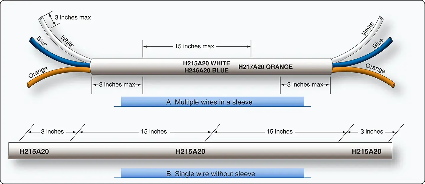 |
| Figure 1. Wire markings for single wire without sleeve |
 |
| Figure 2. Spacing of printed identification marks (indirect marking) |
Types of Wire Markings
The preferred method is to mark directly on the wire without causing insulation degradation. Teflon-coated wires, shielded wiring, multiconductor cable, and thermocouple wires usually require special sleeves to carry identification marks. There are some special wire marking machines available that can be used to stamp directly on the type wires mentioned above. Whatever method of marking is used, the marking should be legible and the color should contrast with the wire insulation or sleeve.
Several different methods can be used to mark directly on the wire: hot stamp marking, ink jet printers, and laser jet printers. [Figure 3] The hot stamp method can damage the insulation of a newer type of wire that utilizes thin insulators. Fracture of the insulation wall and penetration to the conductor of these materials by the stamping dies have occurred. Later in service, when these openings have been wetted by various fluids or moisture, serious arcing and surface tracking have damaged wire bundles.
 |
| Figure 3. Laser wire printer |
Identification sleeves can be used if the direct marking on the wire is not possible. [Figure 4]
 |
| Figure 4. Alternate method of identifying wire bundles |
Flexible sleeving, either clear or opaque, is satisfactory for general use. When color-coded or striped component wire is used as part of a cable, the identification sleeve should specify which color is associated with each wire identification code. Identification sleeves are normally used for identifying the following types of wire or cable: unjacketed shielded wire, thermocouple wire, coaxial cable, multiconductor cable, and high-temperature wire. In most cases, identification tape can be used in place of sleeving. For sleeving exposed to high temperatures (over 400 °F), materials such as silicone fiberglass, should be used. Polyolefin sleeving should be used in areas where resistance to solvent and synthetic hydraulic fluids is necessary. Sleeves may be secured in place with cable ties or by heat shrinking. The identification sleeving for various sizes of wire is shown in Figure 5.
 |
| Figure 5. Recommended size of identification sleeving |
What is the standard interval for aircraft wire identification markings?
What is a CAGE code and why is it on aircraft wiring?
Why is "hot stamp" marking discouraged on modern aircraft wire?
When should indirect marking (sleeving) be used instead of direct marking?
RELATED POSTS