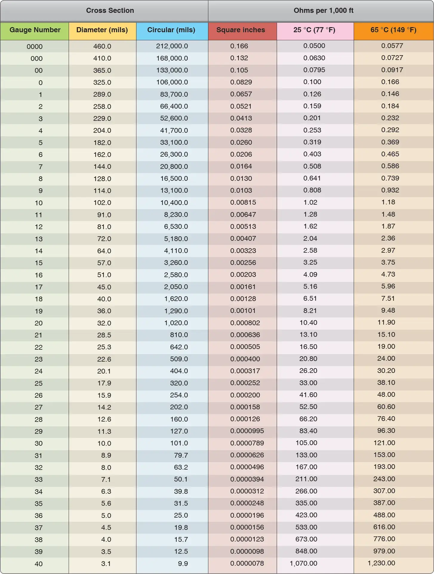
Proper wire size selection is essential in aircraft electrical systems to ensure safe operation, prevent overheating, and maintain acceptable voltage levels. Wire size must be selected based on current load, voltage drop, installation conditions, and environmental factors.
Wire is manufactured in sizes according to a standard known as the American Wire Gauge (AWG). As shown in Figure 1, the wire diameters become smaller as the gauge numbers become larger. Typical wire sizes range from No. 40 to No. 0000 (4/0).
 |
| Figure 1. American wire gauge for standard annealed solid copper wire |
Gauge numbers are useful in comparing the diameter of wires, but not all types of wire or cable can be measured accurately with a gauge. Larger wires are usually stranded to increase their flexibility. In such cases, the total area can be determined by multiplying the area of one strand (usually computed in circular mils when diameter or gauge number is known) by the number of strands in the wire or cable.
Several factors must be considered in selecting the size of wire for transmitting and distributing electric power.
- Wires must have sufficient mechanical strength to allow for service conditions.
- Allowable power loss (I²R loss) in the line represents electrical energy converted into heat. The use of large conductors reduces the resistance and therefore the I²R loss. However, large conductors are more expensive, heavier, and need more substantial support.
- If the source maintains a constant voltage at the input to the lines, any variation in the load on the line causes a variation in line current and a consequent variation in the IR drop in the line. A wide variation in the IR drop in the line causes poor voltage regulation at the load. The obvious remedy is to reduce either current or resistance. A reduction in load current lowers the amount of power being transmitted, whereas a reduction in line resistance increases the size and weight of conductors required. A compromise is generally reached whereby the voltage variation at the load is within tolerable limits and the weight of line conductors is not excessive.
- When current is drawn through the conductor, heat is generated. The temperature of the wire rises until the heat radiated, or otherwise dissipated, is equal to the heat generated by the passage of current through the line. If the conductor is insulated, the heat generated in the conductor is not so readily removed as it would be if the conductor were not insulated. Thus, to protect the insulation from too much heat, the current through the conductor must be maintained below a certain value. When electrical conductors are installed in locations where the ambient temperature is relatively high, the heat generated by external sources constitutes an appreciable part of the total conductor heating. Allowance must be made for the influence of external heating on the allowable conductor current, and each case has its own specific limitations. The maximum allowable operating temperature of insulated conductors varies with the type of conductor insulation being used.
If it is desirable to use wire sizes smaller than #20, particular attention should be given to the mechanical strength and installation handling of these wires (e.g., vibration, flexing, and termination). Wires containing less than 19 strands must not be used. Consideration should be given to the use of high-strength alloy conductors in small-gauge wires to increase mechanical strength. As a general practice, wires smaller than size No. 20 should be provided with additional clamps and be grouped with at least three other wires. They should also have additional support at terminations, such as connector grommets, strain relief clamps, shrinkable sleeving, or telescoping bushings. They should not be used in applications where they are subjected to excessive vibration, repeated bending, or frequent disconnection from screw termination. [Figure 2]
 |
| Figure 2. Conductor chart, continuous (top) and intermittent flow (bottom) |
Current Carrying Capacity
In some instances, the wire may be capable of carrying more current than is recommended for the contacts of the related connector. In this instance, it is the contact rating that dictates the maximum current to be carried by a wire. Wires of larger gauge may need to be used to fit within the crimp range of connector contacts that are adequately rated for the current being carried. Figure 3 gives a family of curves whereby the bundle derating factor may be obtained.
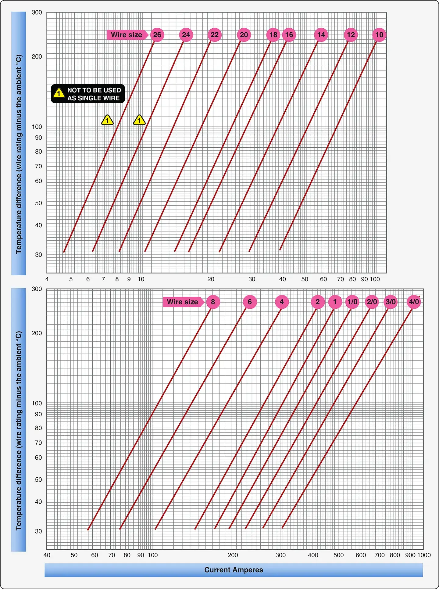 |
| Figure 3. Single copper wire in free air |
Maximum Operating Temperature
The current that causes a temperature steady state condition equal to the rated temperature of the wire should not be exceeded. Rated temperature of the wire may be based upon the ability of either the conductor or the insulation to withstand continuous operation without degradation.
Single Wire in Free Air
Determining a wiring system’s current-carrying capacity begins with determining the maximum current that a given-sized wire can carry without exceeding the allowable temperature difference (wire rating minus ambient °C). The curves are based upon a single copper wire in free air. [Figure 3]
Wires in a Harness
When wires are bundled into harnesses, the current derived for a single wire must be reduced, as shown in Figure 4. The amount of current derating is a function of the number of wires in the bundle and the percentage of the total wire bundle capacity that is being used.
 |
| Figure 4. Bundle derating curve |
Harness at Altitude
Since heat loss from the bundle is reduced with increased altitude, the amount of current should be derated. Figure 5 gives a curve whereby the altitude-derating factor may be obtained.
 |
| Figure 5. Altitude derating curve |
Aluminum Conductor Wire
When aluminum conductor wire is used, sizes should be selected on the basis of current ratings shown in Figure 6. The use of sizes smaller than No. 8 is discouraged. Aluminum wire should not be attached to engine mounted accessories or used in areas having corrosive fumes, severe vibration, mechanical stresses, or where there is a need for frequent disconnection. Use of aluminum wire is also discouraged for runs of less than 3 feet. Termination hardware should be of the type specifically designed for use with aluminum conductor wiring.
 |
| Figure 6. Current-carrying capacity and resistance of aluminum wire |
Computing Current Carrying Capacity
The following section presents some examples on how to calculate the load carrying capacity of aircraft electrical wire. The calculation is a step by step approach and several graphs are used to obtain information to compute the current carrying capacity of a particular wire.
Example 1
Assume a harness (open or braided) consisting of 10 wires, size 20, 200 °C rated copper, and 25 wires size 22, 200 °C rated copper, is installed in an area where the ambient temperature is 60 °C and the aircraft is capable of operating at a 35,000 foot altitude. Circuit analysis reveals that 7 of the 35 wires in the bundle (7⁄35 = 20 percent) are carrying power currents near or up to capacity.
Step 1—Refer to the single wire in free air curves in Figure 7. Determine the change of temperature of the wire to determine free air ratings. Since the wire is in an ambient temperature of 60 °C and rated at 200 °C, the change of the temperature is 200 °C – 60 °C = 140 °C. Follow the 140 °C temperature difference horizontally until it intersects with wire size line on Figure 8. The free air rating for size 20 is 21.5 amps, and the free air rating for size 22 is 16.2 amps.
 |
| Figure 7. Wire harness with protective jacket |
 |
| Figure 8. Shielded wire harness for flight control |
Step 2—Refer to the bundle derating curves in Figure 4. The 20 percent curve is selected since circuit analysis indicates that 20 percent or less of the wire in the harness would be carrying power currents and less than 20 percent of the bundle capacity would be used. Find 35 (on the horizontal axis), since there are 35 wires in the bundle, and determine a derating factor of 0.52 (on the vertical axis) from the 20 percent curve.
Step 3—Derate the size 22 free air rating by multiplying 16.2 by 0.52 to get 8.4 amps in harness rating. Derate the size 20 free air rating by multiplying 21.5 by 0.52 to get 11.2 amps in-harness rating.
Step 4—Refer to the altitude derating curve of Figure 5. Look for 35,000 feet (on the horizontal axis) since that is the altitude at which the aircraft is operating. Note that the wire must be derated by a factor of 0.86 (found on the vertical axis). Derate the size 22 harness rating by multiplying 8.4 amps by 0.86 to get 7.2 amps. Derate the size 20 harness rating by multiplying 11.2 amps by 0.86 to get 9.6 amps.
Step 5—To find the total harness capacity, multiply the total number of size 22 wires by the derated capacity (25 × 7.2 = 180.0 amps) and add to that the number of size 20 wires multiplied by the derated capacity (10 × 9.6 = 96.0 amps) and multiply the sum by the 20 percent harness capacity factor. Thus, the total harness capacity is (180.0 + 96.0) × 0.20 = 55.2 amps. It has been determined that the total harness current should not exceed 55.2 amps, size 22 wire should not carry more than 7.2 amps and size 20 wire should not carry more than 9.6 amps.
Step 6—Determine the actual circuit current for each wire in the bundle and for the whole bundle. If the values calculated in step 5 are exceeded, select the next larger size wire and repeat the calculations.
Example 2
Assume a harness (open or braided), consisting of 12 size 12, 200 °C rated copper wires, is operated in an ambient temperature of 25 °C at sea level and 60 °C at a 20,000-foot altitude. All 12 wires are operated at or near their maximum capacity.
Step 1—Refer to the single wire in free air curve in Figure 3, determine the temperature difference of the wire to determine free air ratings. Since the wire is in ambient temperature of 25 °C and 60 °C and is rated at 200 °C, the temperature differences are 200 °C – 25 °C = 175 °C and 200 °C – 60 °C = 140 °C, respectively. Follow the 175 °C and the 140 °C temperature difference lines on Figure 2 until each intersects wire size line. The free air ratings of size 12 are 68 amps and 59 amps, respectively.
Step 2—Refer to the bundling derating curves in Figure 4. The 100 percent curve is selected because we know all 12 wires are carrying full load. Find 12 (on the horizontal axis) since there are 12 wires in the bundle and determine a derating factor of 0.43 (on the vertical axis) from the 100 percent curve.
Step 3—Derate the size #12 free air ratings by multiplying 68 amps and 59 amps by 0.43 to get 29.2 amps and 25.4 amps, respectively.
Step 4—Refer to the altitude derating curve of Figure 5, look for sea level and 20,000 feet (on the horizontal axis) since these are the conditions at which the load is carried. The wire must be derated by a factor of 1.0 and 0.91, respectively.
Step 5—Derate the size 12 in a bundle ratings by multiplying 29.2 amps at sea level and 25.4 amps at 20,000 feet by 1.0 and 0.91, respectively to obtain 29.2 amps and 23.1 amps. The total bundle capacity at sea level and 25 °C ambient temperature is 29.2 × 12 = 350.4 amps. At 20,000 feet and 60 °C ambient temperature, the bundle capacity is 23.1 × 12=277.2 amps. Each size 12 wire can carry 29.2 amps at sea level, 25 °C ambient temperature or 23.1 amps at 20,000 feet and 60 °C ambient temperature.
Step 6—Determine the actual circuit current for each wire in the bundle and for the bundle. If the values calculated in Step 5 are exceeded, select the next larger size wire and repeat the calculations.
Allowable Voltage Drop
The voltage drop in the main power wires from the generation source or the battery to the bus should not exceed 2 percent of the regulated voltage when the generator is carrying rated current or the battery is being discharged at the 5-minute rate. The tabulation shown in Figure 9 defines the maximum acceptable voltage drop in the load circuits between the bus and the utilization equipment ground.
 |
| Figure 9. Tabulation chart (allowable voltage drop between bus and utilization equipment ground) |
The resistance of the current return path through the aircraft structure is generally considered negligible. However, this is based on the assumption that adequate bonding to the structure or a special electric current return path has been provided that is capable of carrying the required electric current with a negligible voltage drop. To determine circuit resistance, check the voltage drop across the circuit. If the voltage drop does not exceed the limit established by the aircraft or product manufacturer, the resistance value for the circuit may be considered satisfactory. When checking a circuit, the input voltage should be maintained at a constant value. Figures 10 and 11 show formulas that may be used to determine electrical resistance in wires and some typical examples.
 |
| Figure 10. Determining required tin-plated copper wire size and checking voltage drop |
 |
| Figure 11. Determining maximum tin-plated copper wire length and checking voltage drop |
The following formula can be used to check the voltage drop. The resistance/ft can be found in Figures 10 and 11 for the wire size.
Calculated Voltage drop (VD) = resistance/ft × length × current
Electrical Wire Chart Instructions
To select the correct size of electrical wire, two major requirements must be met:
The wire size should be sufficient to prevent an excessive voltage drop while carrying the required current over the required distance. [Figure 9]
The size should be sufficient to prevent overheating of the wire carrying the required current. (See Maximum Operating Temperature for computing current carrying capacity methods.)
To meet the two requirements for selecting the correct wire size using Figure 2, the following must be known:
- The wire length in feet.
- The number of amperes of current to be carried.
- The allowable voltage drop permitted.
- The required continuous or intermittent current.
- The estimated or measured conductor temperature.
- Is the wire to be installed in conduit and/or bundle?
- Is the wire to be installed as a single wire in free air?
Example A
Find the wire size in Figure 2 using the following known information:
- The wire run is 50 feet long, including the ground wire.
- Current load is 20 amps.
- The voltage source is 28 volts from bus to equipment.
- The circuit has continuous operation.
- Estimated conductor temperature is 20 °C or less. The scale on the left of the chart represents maximum wire length in feet to prevent an excessive voltage drop for a specified voltage source system (e.g., 14V, 28V, 115V, 200V). This voltage is identified at the top of scale and the corresponding voltage drop limit for continuous operation at the bottom. The scale (slant lines) on top of the chart represents amperes. The scale at the bottom of the chart represents wire gauge.
Step 1—From the left scale, find the wire length 50 feet under the 28V source column.
Step 2—Follow the corresponding horizontal line to the right until it intersects the slanted line for the 20-amp load.
Step 3—At this point, drop vertically to the bottom of the chart. The value falls between No. 8 and No. 10. Select the next larger size wire to the right, in this case No. 8. This is the smallest size wire that can be used without exceeding the voltage drop limit expressed at the bottom of the left scale. This example is plotted on the wire chart in Figure 2. Use Figure 2 (top) for continuous flow and Figure 2 (bottom) for intermittent flow.
Example B.
Find the wire size in Figure 2 using the following known information:
- The wire run is 200 feet long, including the ground wire.
- Current load is 10 amps.
- The voltage source is 115 volts from bus to equipment.
- The circuit has intermittent operation.
Step 1—From the left scale, find the wire length of 200 feet under the 115V source column.
Step 2—Follow the corresponding horizontal line to the right until it intersects the slanted line for the 10 amp load.
Step 3—At this point, drop vertically to the bottom of the chart. The value falls between No. 16 and No. 14. Select the next larger size wire to the right—in this case, No. 14. This is the smallest size wire that can be used without exceeding the voltage drop limit expressed at the bottom of the left scale.
How does the American Wire Gauge (AWG) numbering system work?
Why must wire current ratings be derated in a harness or at altitude?
What are the specific restrictions for using aluminum conductor wire?
What is the maximum allowable voltage drop for aircraft power wires?
RELATED POSTS