Multiengine aircraft electrical systems are designed with redundancy and reliability in mind. Multiple power sources and interconnected distribution systems ensure continuous electrical supply during normal operation and failure conditions.
Light Multiengine Aircraft
Multiengine aircraft typically fly faster, higher, and farther than single engine aircraft. Multiengine aircraft are designed for added safety and redundancy and, therefore, often contain a more complex power distribution system when compared to light single-engine aircraft. With two engines, these aircraft can drive two alternators (or generators) that supply current to the various loads of the aircraft. The electrical distribution bus system is also divided into two or more systems. These bus systems are typically connected through a series of circuit protectors, diodes, and relays. The bus system is designed to create a power distribution system that is extremely reliable by supplying current to most loads through more than one source.
Paralleling Alternators or Generators
Since two alternators (or generators) are used on twin engine aircraft, it becomes vital to ensure both alternators share the electrical load equally. This process of equalizing alternator outputs is often called paralleling. In general, paralleling is a simple process when dealing with DC power systems found on light aircraft. If both alternators are connected to the same load bus and both alternators produce the same output voltage, the alternators share the load equally. Therefore, the paralleling systems must ensure both power producers maintain system voltage within a few tenths of a volt. For most twin-engine aircraft, the voltage would be between 26.5 volt to 28 volt DC with the alternators operating. A simple vibrating point system used for paralleling alternators is found in Figure 1.
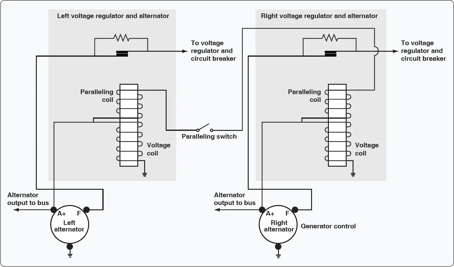 |
| Figure 1. Vibrating point system used for paralleling alternators |
As can be seen in Figure 1, both left and right voltage regulators contain a paralleling coil connected to the output of each alternator. This paralleling coil works in conjunction with the voltage coil of the regulator to ensure proper alternator output. The paralleling coils are wired in series between the output terminals of both alternators. Therefore, if the two alternators provide equal voltages, the paralleling coil has no effect. If one alternator has a higher voltage output, the paralleling coils create the appropriate magnetic force to open/close the contact points, controlling field current and control alternator output.
Today’s aircraft employ solid-state control circuits to ensure proper paralleling of the alternators. Older aircraft use vibrating point voltage regulators or carbon-pile regulators to monitor and control alternator output. For the most part, all carbon-pile regulators have been replaced except on historic aircraft. Many aircraft still maintain a vibrating point system, although these systems are no longer being used on contemporary aircraft.
Power Distribution on Multiengine Aircraft
The power distribution systems found on modern multiengine aircraft contain several distribution points (busses) and a variety of control and protection components to ensure the reliability of electrical power. As aircraft employ more electronics to perform various tasks, the electrical power systems become more complex and more reliable. One means to increase reliability is to ensure more than one power source can be used to power any given load. Another important design concept is to supply critical electrical loads from more than one bus. Twin-engine aircraft, such as a typical corporate jet or commuter aircraft, have two DC generators; they also have multiple distribution busses fed from each generator. Figure 2 shows a simplified diagram of the power distribution system for a twin-engine turboprop aircraft.
 |
| Figure 2. Diagram of the power distribution system for a twin-engine turboprop aircraft |
This aircraft contains two starter generator units used to start the engines and generate DC electrical power. The system is typically defined as a split-bus power distribution system since there is a left and right generator bus that splits (shares) the electrical loads by connecting to each sub-bus through a diode and current limiter. The generators are operated in parallel and share the loads equally.
The primary power supplied for this aircraft is DC, although small amounts of AC are supplied by two inverters. The aircraft diagram shows the AC power distribution at the top and mid left side of the diagram. One inverter is used for main AC power and the second is operated in standby and ready as a backup. Both inverters produce 26-volt AC and 115-volt AC. There is an inverter select relay operated by a pilot controlled switch used to choose which inverter is active.
The hot battery bus (right side of Figure 2) shows a direct connection to the aircraft battery. This bus is always hot if there is a charged battery in the aircraft. Items powered by this bus may include some basics like the entry door lighting and the aircraft clock, which should always have power available. Other items on this bus would be critical to flight safety, such as fire extinguishers, fuel shut offs, and fuel pumps. During a massive system failure, the hot battery bus is the last bus on the aircraft that should fail.
If the battery switch is closed and the battery relay activated, battery power is connected to the main battery bus and the isolation bus. The main battery bus carries current for engine starts and external power. So the main battery bus must be large enough to carry the heaviest current loads of the aircraft. It is logical to place this bus as close as practical to the battery and starters and to ensure the bus is well protected from shorts to ground.
The isolation bus connects to the left and right busses and receives power whenever the main battery bus is energized. The isolation bus connects the output of the left and right generators in parallel. The output of the two generators is then sent to the loads through additional busses. The generator busses are connected to the isolation bus through a fuse known as a current limiter. Current limiters are high amperage fuses that isolate busses if a short circuit occurs. There are several current limiters used in this system for protection between busses. As can be seen in Figure 2, a current limiter symbol looks like two triangles pointed toward each other. The current limiter between the isolation bus and the main generator busses are rated at 325 amps and can only be replaced on the ground. Most current limiters are designed for ground replacement only and only after the malfunction that caused the excess current draw is repaired.
The left and right DC generators are connected to their respective main generator busses. Each generator feeds its respective bus, and since the busses are connected under normal circumstances, the generators operate in parallel. Both generators feed all loads together. If one generator fails or a current limiter opens, the generators can operate independently. This design allows for redundancy in the event of failure and provides battery backup in the event of a dual generator failure.
In the center of Figure 2 are four dual-feed electrical busses. These busses are considered dual-feed since they receive power from both the left and right generator busses. If a fault occurs, either generator bus can power any or all loads on a dual-feed bus. During the design phase of the aircraft, the electrical loads must be evenly distributed between each of the dual-feed busses. It is also important to power redundant systems from different busses. For example, the pilot’s windshield heat would be powered by a different bus from the one that powers the copilot’s windshield heat. If one bus fails, at least one windshield heat continues to work properly, and the aircraft can be landed safely in icing conditions.
Notice that the dual-feed busses are connected to the main generator busses through both a current limiter and a diode. Remember, a diode allows current flow in only one direction. [Figure 3]
 |
| Figure 3. Dual-feed bus system |
The current can flow from the generator bus to the dual-feed bus, but the current cannot flow from the dual fed bus to the main generator bus. The diode is placed in the circuit so the main bus must be more positive than the sub bus for current flow. This circuit also contains a current limiter and a circuit breaker. The circuit breaker is located on the flight deck and can be reset by the pilot. The current limiter can only be replaced on the ground by a technician. The circuit breaker is rated at a slightly lower current value than the current limiter; therefore, the circuit breaker should open if a current overload exists. If the circuit breaker fails to open, the current limiter provides backup protection and disconnects the circuit.
Large Multiengine Aircraft
Transport category aircraft typically carry hundreds of passengers and fly thousands of miles each trip. Therefore, large aircraft require extremely reliable power distribution systems that are computer controlled. These aircraft have multiple power sources (AC generators) and a variety of distribution busses. A typical airliner contains two or more main AC generators driven by the aircraft turbine engines, as well as more than one backup AC generator. DC systems are also employed on large aircraft and the ship’s battery is used to supply emergency power in case of a multiple failures.
The AC generator (sometimes called an alternator) produces three-phase 115-volt AC at 400 Hz. AC generators. Since most modern transport category aircraft are designed with two engines, there are two main AC generators. The APU also drives an AC generator. This unit is available during flight if one of the main generators fails. The main and auxiliary generators are typically similar in output capacity and supply a maximum of 110 kilovolt-amperes (kVA). A fourth generator, driven by an emergency ram air turbine, is also available in the event the two main generators and one auxiliary generator fail. The emergency generator is typically smaller and produces less power. With four AC generators available on modern aircraft, it is highly unlikely that a complete power failure occurs. However, if all AC generators are lost, the aircraft battery will continue to supply DC electrical power to operate vital systems.
AC Power Systems
Transport category aircraft use large amounts of electrical power for a variety of systems. Passenger comfort requires power for lighting, audio-visual systems, and galley power for food warmers and beverage coolers. A variety of electrical systems are required to fly the aircraft, such as flight control systems, electronic engine controls, communication, and navigation systems. The output capacity of one engine-driven AC generator can typically power all necessary electrical systems. A second engine-driven generator is operated during flight to share the electrical loads and provide redundancy.
The complexity of multiple generators and a variety of distribution busses requires several control units to maintain a constant supply of safe electrical power. The AC electrical system must maintain a constant output of 115 to 120 volts at a frequency of 400 Hz (±10 percent). The system must ensure power limits are not exceeded. AC generators are connected to the appropriate distribution busses at the appropriate time, and generators are in phase when needed. There is also the need to monitor and control any external power supplied to the aircraft, as well as control of all DC electrical power.
Two electronic line-replaceable units (LRUs) are used to control the electrical power on a typical large aircraft. The generator control unit (GCU) is used for control of AC generator functions, such as voltage regulation and frequency control. The bus power control unit (BPCU) is used to control the distribution of electrical power between the various distribution busses on the aircraft. The GCU and BPCU work together to control electrical power, detect faults, take corrective actions when needed, and report any defect to the pilots and the aircraft’s central maintenance system. There is typically one GCU for each AC generator and at least one BPCU to control bus connections. These LRUs are located in the aircraft’s electronics equipment bay and are designed for easy replacement.
When the pilot calls for generator power by activating the generator control switch on the flight deck, the GCU monitors the system to ensure correct operation. If all systems are operating within limits, the GCU energizes the appropriate generator circuits and provides voltage regulation for the system. The GCU also monitors AC output to ensure a constant 400-Hz frequency. If the generator output is within limits, the GCU then connects the electrical power to the main generator bus through an electrical contactor (solenoid). These contactors are often called generator breakers (GB) since they break (open) or make (close) the main generator circuit.
After generator power is available, the BPCU activates various contactors to distribute the electrical power. The BPCU monitors the complete electrical system and communicates with the GCU to ensure proper operation. The BPCU employs remote current sensors known as a current transformer (CT) to monitor the system. [Figure 4]
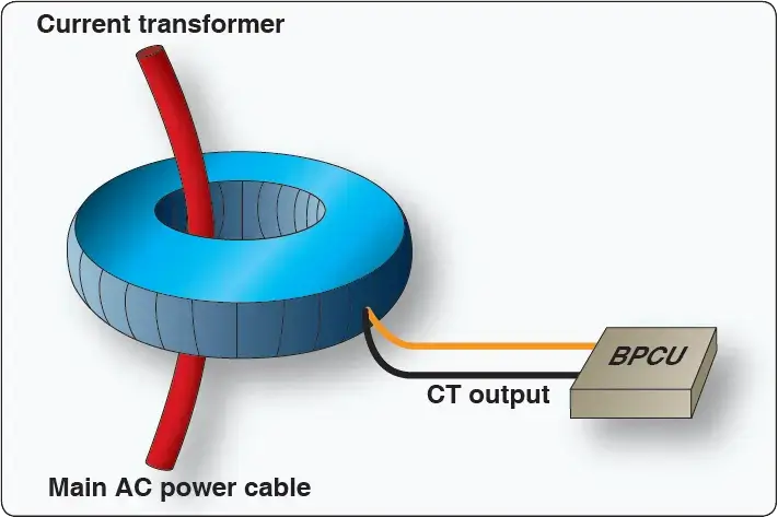 |
| Figure 4. Current transformer |
A CT is an inductive unit that surrounds the main power cables of the electrical distribution system. As AC power flows through the main cables, the CT receives an induced voltage. The amount of CT voltage is directly related to the current flowing through the cable. The CT connects to the BPCU, which allows accurate current monitoring of the system. A typical aircraft employs several CTs throughout the electrical system.
The BPCU is a dedicated computer that controls the electrical connections between the various distribution busses found on the aircraft. The BPCU uses contactors (solenoids) called bus tie breakers (BTB) for connection of various circuits. These BTBs open/close the connections between the busses as needed for system operation as called for by the pilots and the BPCU. This sounds like a simple task, yet to ensure proper operation under a variety of conditions, the bus system becomes very complex. There are three common types of distribution bus systems found on transport category aircraft: split bus, parallel bus, and split parallel.
Split-Bus Power Distribution Systems
Modern twin-engine aircraft, such as the Boeing 737, 757, 777, Airbus A-300, A-320, and A-310, employ a split-bus power distribution system. During normal conditions, each engine-driven AC generator powers only one main AC bus. The busses are kept split from each other, and two generators can never power the same bus simultaneously. This is very important since the generator output current is not phase regulated. (If two out-of-phase generators were connected to the same bus, damage to the system would occur.) The split-bus system does allow both engine-driven generators to power any given bus, but not at the same time. Generators must remain isolated from each other to avoid damage. The GCUs and BPCU ensure proper generator operation and power distribution.
On all modern split bus systems, the APU can be started and operated during flight. This allows the APU generator to provide back-up power in the event of a main generator failure. A fourth emergency generator powered by the ram air turbine is also available if the other generators fail.
The four AC generators are shown at the bottom of Figure 5. These generators are connected to their respective busses through the generator breakers. For example, generator 1 sends current through GB1 to AC bus 1. AC bus 1 feeds a variety of primary electrical loads, and also feeds sub-busses that in turn power additional loads.
 |
| Figure 5. Schematic of split-bus power distribution system |
With both generators operating and all systems normal, AC bus 1 and AC bus 2 are kept isolated. Typically during flight, the APB (bottom center of Figure 5) would be open and the APU generator off; the emergency generator (bottom right) would also be off and disconnected. If generator one should fail, the following happens:
- The GB 1 is opened by the GCU to disconnect the failed generator.
- The BPCU closes BTB 1 and BTB 2. This supplies AC power to AC bus 1 from generator 2.
- The pilots start the APU and connect the APU generator. At that time, the BPCU and GCUs move the appropriate BTBs to correctly configure the system so the APU powers bus 1 and generator 2 powers bus 2. Once again, two AC generators operate independently to power AC bus 1 and 2.
If all generators fail, AC is also available through the static inverter (center of Figure 5). The inverter is powered from the hot battery bus and used for essential AC loads if all AC generators fail. Of course, the GCUs and BPCU take the appropriate actions to disconnect defective units and continue to feed essential AC loads using inverter power.
To produce DC power, AC bus 1 sends current to its transformer rectifier (TR), TR 1 (center left of Figure 5). The TR unit is used to change AC to DC. The TR contains a transformer to step down the voltage from 115-volt AC to 26-volt AC and a rectifier to change the 26-volt AC to 26- volt DC. The output of the TR is therefore compatible with the aircraft battery at 26-volt DC. Since DC power is not phase sensitive, the DC busses are connected during normal operation. In the event of a bus problem, the BPCU may isolate one or more DC busses to ensure correct distribution of DC power. This aircraft contains two batteries that are used to supply emergency DC power.
Parallel Systems
Multiengine aircraft, such as the Boeing 727, MD-11, and the early Boeing 747, employ a parallel power distribution system. During normal flight conditions, all engine-driven generators connect together and power the AC loads. In this configuration, the generators are operated in parallel; hence the name parallel power distribution system. In a parallel system, all generator output current must be phase regulated. Before generators are connected to the same bus, their output frequency must be adjusted to ensure the AC output reaches the positive and negative peaks simultaneously. During the flight, generators must maintain this in-phase condition for proper operation.
One advantage of parallel systems is that in the event of a generator failure, the busses are already connected and the defective generator need only be isolated from the system. A paralleling bus, or synchronizing bus, is used to connect the generators during flight. The synchronizing bus is often referred to as the sync bus. Most of these systems are less automated and require that flight crew monitor systems and manually control bus contactors. BTBs are operated by the flight crew through the electrical control panel and used to connect all necessary busses. GBs are used to connect and disconnect the generators.
Figure 6 shows a simplified parallel power distribution system. This aircraft employs three main-engine driven generators and one APU generator. The APU (bottom right) is not operational in flight and cannot provide backup power. The APU generator is for ground operations only. The three main generators (bottom of Figure 6) are connected to their respective AC bus through GBs one, two, and three. The AC busses are connected to the sync bus through three BTBs. In this manner, all three generators share the entire AC electrical loads. Keep in mind, all generators connected to the sync bus must be in phase. If a generator fails, the flight crew would simply isolate the defective generator and the flight would continue without interruption.
 |
| Figure 6. Parallel power distribution system |
The number one and two DC busses (Figure 6 top left) are used to feed the DC electrical loads of the aircraft. DC bus 1 receives power form AC bus 1 through TR1. DC bus 2 is fed in a similar manner from AC bus 2. The DC busses also connect to the battery bus and eventually to the battery. The essential DC bus (top left) can be fed from DC bus 1 or the essential TR. A diode prevents the essential DC bus from powering DC bus 1. The essential DC bus receives power from the essential TR, which receives power from the essential AC bus. This provides an extra layer of redundancy since the essential AC bus can be isolated and fed from any main generator. Figure 6 shows generator 3 powering the essential AC bus.
Split-Parallel Systems
A split-parallel bus basically employs the best of both split-bus and the parallel-bus systems. The split-parallel system is found on the Boeing 747-400 and contains four generators driven by the main engines and two APU-driven generators. The system can operate with all generators in parallel, or the generators can be operated independently as in a split-bus system. During a normal flight, all four engine-driven generators are operated in parallel. The system is operated in split-bus mode only under certain failure conditions or when using external power. The Boeing 747-400 split-parallel system is computer controlled using four GCUs and two BPCUs. There is one GCU controlling each generator; BPCU 1 controls the left side bus power distribution, and BPCU 2 controls the right side bus power. The GCUs and BPCUs operate similarly to those previously discussed under the split-bus system.
Figure 7 shows a simplified split-parallel power distribution system. The main generators (top of Figure 7) are driven by the main turbine engines. Each generator is connected to its load bus through a generator control breaker (GCB). The generator control unit closes the GCB when the pilot calls for generator power and all systems are operating normally. Each load bus is connected to various electrical systems and additional sub-busses. The BTBs are controlled by the BPCU and connect each load bus to the left and right sync bus. A split systems breaker (SSB) is used to connect the left and right sync busses and is closed during a normal flight. With the SSB, GCBs, and BTBs, in the closed position the generators operate in parallel. When operating in parallel, all generators must be in phase.
 |
| Figure 7. Split-parallel distribution system |
If the aircraft electrical system experiences a malfunction, the control units make the appropriate adjustments to ensure all necessary loads receive electrical power. For example, if generator 1 fails, GCU 1 detects the fault and command GCB 1 to open. With GCB 1 open, load bus 1 now feeds from the sync bus and the three operating generators. In another example, if load bus 4 should short to ground, BPCU 4 opens the GCB 4 and BTB 4. This isolates the shorted bus (load bus 4). All loads on the shorted bus are no longer powered, and generator 4 is no longer available. However, with three remaining generators operational, the flight continues safely.
As do all large aircraft, the Boeing 747-400 contains a DC power distribution system. The DC system is used for battery and emergency operations. The DC system is similar to those previously discussed, powered by TR units. The TRs are connected to the AC busses and convert AC into 26-volt DC. The DC power systems are the final backups in the event of a catastrophic electrical failure. The systems most critical to fly the aircraft can typically receive power from the battery. This aircraft also contains two static inverters to provide emergency AC power when needed.
What does it mean to "parallel" aircraft alternators or generators?
What is a current limiter and how does it differ from a circuit breaker?
Why must AC generators be "in phase" in a parallel distribution system?
What is the function of a Transformer Rectifier (TR) unit?
RELATED POSTS