Electrical system components such as switches, relays, solenoids, and circuit protection devices are essential for controlling and protecting aircraft electrical systems.
Switches
Switches are devices that open and close circuits. They consist of one or more pairs of contacts. The current in the circuit flows when the contacts are closed. Switches with momentary contacts actuate the circuit temporarily, and they return to the normal position with an internal spring when the switch is released. Switches with continuous contacts remain in position when activated. Hazardous errors in switch operation can be avoided by logical and consistent installation. Two-position on/off switches should be mounted so that the on position is reached by an upward or forward movement of the toggle. When the switch controls movable aircraft elements, such as landing gear or flaps, the toggle should move in the same direction as the desired motion. Inadvertent operation of a switch can be prevented by mounting a suitable guard over the switch. [Figure 1]
 |
| Figure 1. Switch guard |
A specifically designed switch should be used in all circuits where a switch malfunction would be hazardous. Such switches are of rugged construction and have sufficient contact capacity to break, make, and continuously carry the connected load current. Snap-action design is generally preferred to obtain rapid opening and closing of contacts regardless of the speed of the operating toggle or plunger, thereby minimizing contact arcing.
The nominal current rating of the conventional aircraft switch is usually stamped on the switch housing. This rating represents the continuous current rating with the contacts closed. Switches should be derated from their nominal current rating for the following types of circuits:
- High rush-in circuits—contain incandescent lamps that can draw an initial current up to 15 times greater than the continuous current. Contact burning or welding may occur when the switch is closed.
- Inductive circuits—magnetic energy stored in solenoid coils or relays is released and appears as an arc when the control switch is opened.
- Motors—DC motors draw several times their rated current during starting, and magnetic energy stored in their armature and field coils is released when the control switch is opened.
Figure 2 is used for selecting the proper nominal switch rating when the continuous load current is known. This selection is essentially a derating to obtain reasonable switch efficiency and service life.
 |
| Figure 2. Derating table for switches |
Type of Switches
Single-pole single-throw (SPST)—opens and closes a single circuit. Pole indicates the number of separate circuits that can be activated, and throw indicates the number of current paths.
Double-pole single-throw (DPST)—turn two circuits on and off with one lever.
Single-pole double-throw (SPDT)—route circuit current to either of two paths. The switch is ON in both positions. For example, switch turns on red lamp in one position and turns on green lamp in the other position.
Double-pole double-throw (DPDT)—activates two separate circuits at the same time.
Double-throw switches—have either two or three positions.
Two-position switch—pole always connected to one of the two throws. Three-position switches have a center OFF position that disconnects the pole from both throws.
Spring loaded switches—available in two types: (1) normally open (NO) and (2) normally closed (NC). The contacts of the NO switch are disconnected in the normal position and close when the switch is activated. The switch returns to the normal position when the applied force to the switch is released. The contacts of the NC switch are connected in the normal position and open when the switch is activated. The switch returns to the normal position when the applied force to the switch is released.
Toggle and Rocker Switches
Toggle and rocker switches control most of the aircraft’s electrical components. [Figure 3] Aircraft that are outfitted with a glass cockpit often use push buttons to control electrical components.
 |
| Figure 3. Toggle and rocker switches |
Rotary Switches
Rotary switches are activated by twisting a knob or shaft and are commonly found on radio control panels. Rotary switches are utilized for controlling more than two circuits.
Precision (Micro) Switches
Micro switches require very little pressure to activate. These types of switches are spring loaded, once the pressure is removed, the contacts return to the normal position. These types of switches are typically single pole double throw (SPDT) or double pole double throw (DPDT) and have three contacts: normally open, normally closed, and common. Micro switches are used to detect position or to limit travel of moving parts, such as landing gear, flaps, spoilers, etc. [Figure 4]
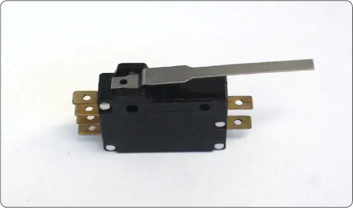 |
| Figure 4. A micro switch |
Relays and Solenoids (Electromagnetic Switches)
Relays are used to control the flow of large currents using a small current. A low-power DC circuit is used to activate the relay and control the flow of large AC currents. They are used to switch motors and other electrical equipment on and off and to protect them from overheating. A solenoid is a special type of relay that has a moving core. The electromagnet core in a relay is fixed. Solenoids are mostly used as mechanical actuators but can also be used for switching large currents. Relays are only used to switch currents.
Solenoids
Solenoids are used as switching devices where a weight reduction can be achieved or electrical controls can be simplified. The foregoing discussion of switch ratings is generally applicable to solenoid contact ratings. Solenoids have a movable core (armature) that is usually made of steel or iron, and the coil is wrapped around the armature. The solenoid has an electromagnetic tube and the armature moves in and out of the tube. [Figure 5]
 |
| Figure 5. Solenoid |
Relays
The two main types of relays are electromechanical and solid-state. Electromechanical relays have a fixed core and a moving plate with contacts on it, while solid-state relays work similarly to transistors and have no moving parts. Current flowing through the coil of an electromechanical relay creates a magnetic field that attracts a lever and changes the switch contacts. The coil current can be on or off so relays have two switch positions, and they are double throw switches. Residual magnetism is a common problem and the contacts may stay closed or may open by a slight amount of residual magnetism. A relay is an electrically operated switch and is therefore subject to dropout under low system voltage conditions. Relays allow one circuit to switch a second circuit that can be completely separate from the first. For example, a low voltage DC battery circuit can use a relay to switch a 110-volt three-phase AC circuit. There is no electrical connection inside the relay between the two circuits; the link is magnetic and mechanical. [Figure 6]
 |
| Figure 6. Relay |
Current Limiting Devices
Conductors should be protected with circuit breakers or fuses located as close as possible to the electrical power source bus. Normally, the manufacturer of the electrical equipment specifies the fuse or circuit breaker to be used when installing equipment. The circuit breaker or fuse should open the circuit before the conductor emits smoke. To accomplish this, the time-current characteristic of the protection device must fall below that of the associated conductor. Circuit protector characteristics should be matched to obtain the maximum utilization of the connected equipment. Figure 7 shows a chart used in selecting the circuit breaker and fuse protection for copper conductors. This limited chart is applicable to a specific set of ambient temperatures and wire bundle sizes and is presented as typical only. It is important to consult such guides before selecting a conductor for a specific purpose. For example, a wire run individually in the open air may be protected by the circuit breaker of the next higher rating to that shown on the chart.
 |
| Figure 7. Wired and circuit protection chart |
Fuses
A fuse is placed in series with the voltage source and all current must flow through it. [Figure 8] The fuse consists of a strip of metal that is enclosed in a glass or plastic housing. The metal strip has a low melting point and is usually made of lead, tin, or copper. When the current exceeds the capacity of the fuse the metal strip heats up and breaks. As a result of this, the flow of current in the circuit stops.
 |
| Figure 8. A fuse |
There are two basic types of fuses: fast acting and slow blow. The fast-acting type opens very quickly when their particular current rating is exceeded. This is important for electric devices that can quickly be destroyed when too much current flows through them for even a very small amount of time. Slow blow fuses have a coiled construction inside. They are designed to open only on a continued overload, such as a short circuit.
Circuit Breakers
A circuit breaker is an automatically operated electrical switch designed to protect an electrical circuit from damage caused by an overload or short circuit. Its basic function is to detect a fault condition and immediately discontinue electrical flow. Unlike a fuse that operates once and then has to be replaced, a circuit breaker can be reset to resume normal operation. All resettable circuit breakers should open the circuit in which they are installed regardless of the position of the operating control when an overload or circuit fault exists. Such circuit breakers are referred to as trip-free. Automatic reset circuit breakers automatically reset themselves. They should not be used as circuit protection devices in aircraft. When a circuit breaker trips, the electrical circuit should be checked and the fault removed before the circuit breaker is reset. Sometimes circuit breakers trip for no apparent reason, and the circuit breaker can be reset one time. If the circuit breaker trips again, there exists a circuit fault and the technician must troubleshoot the circuit before resetting the circuit breaker. [Figure 9]
 |
| Figure 9. Circuit breaker panel |
Some new aircraft designs use a digital circuit protection architecture. This system monitors the amperage through a particular circuit. When the maximum amperage for that circuit is reached, the power is rerouted away from the circuit. This system reduces the use of mechanical circuit breakers. The advantages are weight savings and the reduction of mechanical parts.
What is a "trip-free" circuit breaker and why is it required?
Why must switches be derated for inductive or motor circuits?
How does a solenoid differ from a standard relay?
What is the difference between a fast-acting fuse and a slow-blow fuse?
RELATED POSTS