Aircraft lighting systems are essential for safe operation during night flight and low-visibility conditions. They provide visibility for pilots, enhance aircraft recognition by others, and assist in both normal and emergency operations.
Aircraft lighting systems provide illumination for both exterior and interior operations. Lights on the exterior provide illumination for such operations as landing at night, inspection of icing conditions, and enhance safety by reducing the risk of midair collision. Interior lighting provides illumination for instruments, cockpits, cabins, and other areas occupied by crewmembers and passengers. Certain special lights, such as indicator and warning lights, indicate the operation status of equipment.
Exterior Lights
Position, anticollision, landing, and taxi lights are common examples of aircraft exterior lights. Some lights are required for night operations. Other types of exterior lights, such as wing inspection lights, are of great benefit for specialized flying operations.
Position Lights
Aircraft operating at night must be equipped with position lights that meet the minimum requirements specified by Title 14 of the Code of Federal Regulations. A set of position lights consists of one red, one green, and one white light. [Figure 1 and 2]
 |
| Figure 1. A left wing tip position light (red) and a white strobe light |
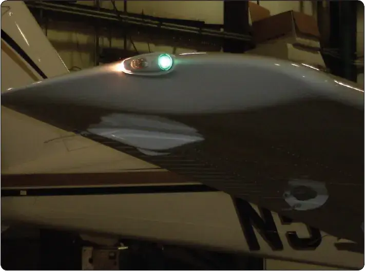 |
| Figure 2. A right wing tip position light, also known as a navigation light |
On some types of installations, a switch in the cockpit provides for steady or flashing operation of the position lights. On many aircraft, each light unit contains a single lamp mounted on the aircraft surface. Other types of position light units contain two lamps and are often streamlined into the surface of the aircraft structure.
The green light unit is always mounted at the extreme tip of the right wing. The red unit is mounted in a similar position on the left wing. The white unit is usually located on the vertical stabilizer in a position where it is clearly visible through a wide angle from the rear of the aircraft. Figure 3 illustrates a schematic diagram of a position light circuit. Position lights are also known as navigation lights.
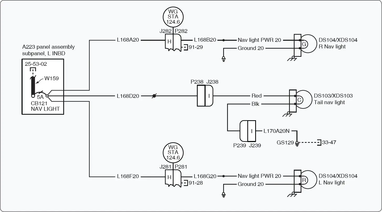 |
| Figure 3. Navigation light system schematic |
There are many variations in position light circuits used on different aircraft. All circuits are protected by fuses or circuit breakers, and many circuits include flashing and dimming equipment. Small aircraft are usually equipped with a simplified control switch and circuitry. In some cases, one control knob or switch is used to turn on several sets of lights; for example, one design uses a control knob, the first movement of which turns on the position lights and the instrument panel lights. Further rotation of the control knob increases the intensity of only the panel lights. A flasher unit is seldom included in the position light circuitry of very light aircraft but is used in small twin-engine aircraft. Traditional position lights use incandescent light bulbs. LED lights have been introduced on modern aircraft because of their good visibility, high reliability, and low power consumption.
Anticollision Lights
An anticollision light system may consist of one or more lights. They are rotating beam lights that are usually installed on top of the fuselage or tail in such a location that the light does not affect the vision of the crewmember or detract from the visibility of the position lights. Large transport-type aircraft use an anticollision light on top and one on the bottom of the aircraft. Figure 4 shows a typical anticollision light installation in a vertical stabilizer.
 |
| Figure 4. Anticollision lights |
An anticollision light unit usually consists of one or two rotating lights operated by an electric motor. The light may be fixed but mounted beneath rotating mirrors inside a protruding red glass housing. The mirrors rotate in an arc, and the resulting flash rate is between 40 and 100 flashes per minute. Newer aircraft designs use an LED type of anticollision light. The anticollision light is a safety light to warn other aircraft, especially in congested areas.
A white strobe light is a second type of anticollision light that is also common. Usually mounted at the wingtips and, possibly, at empennage extremities, strobe lights produce an extremely bright intermittent flash of white light that is highly visible. The light is produced by a high voltage discharge of a capacitor. A dedicated power pack houses the capacitor and supplies voltage to a sealed xenon-filled tube. The xenon ionizes with a flash when the voltage is applied. A strobe light is shown in Figure 1.
Landing and Taxi Lights
Landing lights are installed in aircraft to illuminate runways during night landings. These lights are very powerful and are directed by a parabolic reflector at an angle providing a maximum range of illumination. Landing lights of smaller aircraft are usually located midway in the leading edge of each wing or streamlined into the aircraft surface. Landing lights for larger transport-category aircraft are usually located in the leading edge of the wing close to the fuselage. Each light may be controlled by a relay, or it may be connected directly into the electric circuit. On some aircraft, the landing light is mounted in the same area with a taxi light. [Figure 5] A sealed beam, halogen, or high intensity xenon discharge lamp is used.
 |
| Figure 5. Landing lights |
Taxi lights are designed to provide illumination on the ground while taxiing or towing the aircraft to or from a runway, taxi strip, or in the hangar area. [Figure 6] Taxi lights are not designed to provide the degree of illumination necessary for landing lights. On aircraft with tricycle landing gear, either single or multiple taxi lights are often mounted on the non‑steerable part of the nose landing gear. They are positioned at an oblique angle to the centerline of the aircraft to provide illumination directly in front of the aircraft and also some illumination to the right and left of the aircraft’s path. On some aircraft, the dual taxi lights are supplemented by wingtip clearance lights controlled by the same circuitry. Taxi lights are also mounted in the recessed areas of the wing leading edge, often in the same area with a fixed landing light.
 |
| Figure 6. Taxi lights |
Many small aircraft are not equipped with any type of taxi light, but rely on the intermittent use of a landing light to illuminate taxiing operations. Still other aircraft utilize a dimming resistor in the landing light circuit to provide reduced illumination for taxiing. A typical circuit for taxi lights is shown in Figure 7.
 |
| Figure 7. Taxi light circuit |
Some large aircraft are equipped with alternate taxi lights located on the lower surface of the aircraft, aft of the nose radome. These lights, operated by a separate switch from the main taxi lights, illuminate the area immediately in front of and below the aircraft nose.
Wing Inspection Lights
Some aircraft are equipped with wing inspection lights to illuminate the leading edge of the wings to permit observation of icing conditions and general condition of these areas in flight. These lights permit visual detection of ice formation on wing leading edges while flying at night. They are usually controlled through a relay by an on/off toggle switch in the cockpit. Some wing inspection light systems may include or be supplemented by additional lights, sometimes called nacelle lights, that illuminate adjacent areas, such as cowl flaps or the landing gear. These are normally the same type of lights and can be controlled by the same circuits.
Interior Lights
Aircraft are equipped with interior lights to illuminate the cabin. [Figure 8] Often white and red light settings are provided. Commercial aircraft have a lighting system that illuminates the main cabin, an independent lighting system so that passengers can read when the cabin lights are off, and an emergency lighting system on the floor of the aircraft to aid passengers of the aircraft during an emergency.
 |
| Figure 7. Interior cockpit and cabin light system |
Maintenance and Inspection of Lighting Systems
Inspection of an aircraft’s lighting system normally includes checking the condition and security of all visible wiring, connections, terminals, fuses, and switches. A continuity tester or meter can be used in making these checks, since many faults can be located by systematically testing each circuit for continuity.
What is the standard color and location for aircraft position lights?
What are the different types of anticollision lights?
How do landing lights differ from taxi lights?
Why are wing inspection lights used during night flight?
RELATED POSTS