Generator control systems regulate output voltage, protect electrical components, and ensure reliable operation under varying flight conditions. These systems automatically adjust generator performance to meet changing electrical demands.
Theory of Generator Control
All aircraft are designed to operate within a specific voltage range (for example, 13.5–14.5 volts). And since aircraft operate at a variety of engine speeds (remember, the engine drives the generator) and with a variety of electrical demands, all generators must be regulated by a control system. The generator control system is designed to keep the generator output within limits for all flight variables. Generator control systems are often referred to as voltage regulators or generator control units (GCU).
Aircraft generator output can easily be adjusted through control of the generator’s magnetic field strength. Remember, the strength of the magnetic field has a direct effect on generator output. More field current means more generator output and vice versa. Figure 1 shows a simple generator control used to adjust field current. When field current is controlled, generator output is controlled. Keep in mind, this system is manually adjusted and would not be suitable for aircraft. Aircraft systems must be automatic and are therefore a bit more complex.
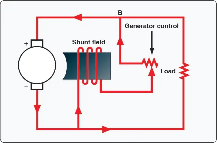 |
| Figure 1. Regulation of generator voltage by field rheostat |
There are two basic types of generator controls: electromechanical and solid-state (transistorized). The electromechanical type controls are found on older aircraft and tend to require regular inspection and maintenance. Solid-state systems are more modern and typically considered to have better reliability and more accurate generator output control.
Functions of Generator Control Systems
Most generator control systems perform a number of functions related to the regulation, sensing, and protection of the DC generation system. Light aircraft typically require a less complex generator control system than larger multiengine aircraft. Some of the functions listed below are not found on light aircraft.
Voltage Regulation
The most basic of the GCU functions is that of voltage regulation. Regulation of any kind requires the regulation unit to take a sample of a generator output and compare that sample to a known reference. If the generator’s output voltage falls outside of the set limits, then the regulation unit must provide an adjustment to the generator field current. Adjusting field current controls generator output.
Overvoltage Protection
The overvoltage protection system compares the sampled voltage to a reference voltage. The overvoltage protection circuit is used to open the relay that controls the field excitation current. It is typically found on more complex generator control systems.
Parallel Generator Operations
On multiengine aircraft, a paralleling feature must be employed to ensure all generators operate within limits. In general, paralleling systems compare the voltages between two or more generators and adjust the voltage regulation circuit accordingly.
Overexcitation Protection
When one generator in a paralleled system fails, one of the generators can become overexcited and tends to carry more than its share of the load, if not all of the loads. Basically, this condition causes the generator to produce too much current. If this condition is sensed, the overexcited generator must be brought back within limits, or damage occurs. The overexcitation circuit often works in conjunction with the overvoltage circuit to control the generator.
Differential Voltage
This function of a control system is designed to ensure all generator voltage values are within a close tolerance before being connected to the load bus. If the output is not within the specified tolerance, then the generator contactor is not allowed to connect the generator to the load bus.
Reverse Current Sensing
If the generator cannot maintain the required voltage level, it eventually begins to draw current instead of providing it. This situation occurs, for example, if a generator fails. When a generator fails, it becomes a load to the other operating generators or the battery. The defective generator must be removed from the bus. The reverse current sensing function monitors the system for a reverse current. Reverse current indicates that current is flowing to the generator not from the generator. If this occurs, the system opens the generator relay and disconnects the generator from the bus.
Generator Controls for High Output Generators
Most modern high output generators are found on turbine powered corporate-type aircraft. These small business jets and turboprop aircraft employ a generator and starter combined into one unit. This unit is referred to as a starter generator. A starter generator has the advantage of combining two units into one housing, saving space and weight. Since the starter-generator performs two tasks, engine starting and generation of electrical power, the control system for this unit is relatively complex.
A simple explanation of a starter-generator shows that the unit contains two sets of field windings. One field is used to start the engine and one used for the generation of electrical power. [Figure 2]
 |
| Figure 2. Starter-generator |
During the start function, the GCU must energize the series field and the armature causes the unit to act like a motor. During the generating mode, the GCU must disconnect the series field, energize the parallel field, and control the current produced by the armature. At this time, the starter generator acts like a typical generator. Of course, the GCU must perform all the functions described earlier to control voltage and protect the system. These functions include voltage regulation, reverse current sensing, differential voltage, overexcitation protection, overvoltage protection, and parallel generator operations. A typical GCU is shown in Figure 3.
 |
| Figure 3. Generator control unit (GCU) |
In general, modern GCUs for high-output generators employ solid-state electronic circuits to sense the operations of the generator or starter-generator. The circuitry then controls a series of relays and/or solenoids to connect and disconnect the unit to various distribution busses. One unit found in almost all voltage regulation circuitry is the zener diode. The zener diode is a voltage sensitive device that is used to monitor system voltage. The zener diode, connected in conjunction to the GCU circuitry, then controls the field current, which in turn controls the generator output.
Generator Controls for Low-Output Generators
A typical generator control circuit for low-output generators modifies current flow to the generator field to control generator output power. As flight variables and electrical loads change, the GCU must monitor the electrical system and make the appropriate adjustments to ensure proper system voltage and current. The typical generator control is referred to as a voltage regulator or a GCU.
Since most low-output generators are found on older aircraft, the control systems for these systems are electromechanical devices. (Solid-state units are found on more modern aircraft that employ DC alternators and not DC generators.) The two most common types of voltage regulator are the carbon pile regulator and the three-unit regulator. Each of these units controls field current using a type of variable resistor. Controlling field current then controls generator output. A simplified generator control circuit is shown in Figure 4.
 |
| Figure 4. Voltage regulator for low-output generator |
Carbon Pile Regulators
The carbon pile regulator controls DC generator output by sending the field current through a stack of carbon disks (the carbon pile). The carbon disks are in series with the generator field. If the resistance of the disks increases, the field current decreases and the generator output goes down. If the resistance of the disks decreases, the field current increases and generator output goes up. As seen in Figure 5, a voltage coil is installed in parallel with the generator output leads. The voltage coil acts like an electromagnet that increases or decrease strength as generator output voltage changes. The magnetism of the voltage coil controls the pressure on the carbon stack. The pressure on the carbon stack controls the resistance of the carbon; the resistance of the carbon controls field current and the field current controls generator output.
 |
| Figure 5. Carbon pile regulator |
Carbon pile regulators require regular maintenance to ensure accurate voltage regulation; therefore, most have been replaced on aircraft with more modern systems.
Three-Unit Regulators
The three-unit regulator used with DC generator systems is made of three distinct units. Each of these units performs a specific function vital to correct electrical system operation. A typical three-unit regulator consists of three relays mounted in a single housing. Each of the three relays monitors generator outputs and opens or closes the relay contact points according to system needs. A typical three-unit regulator is shown in Figure 6.
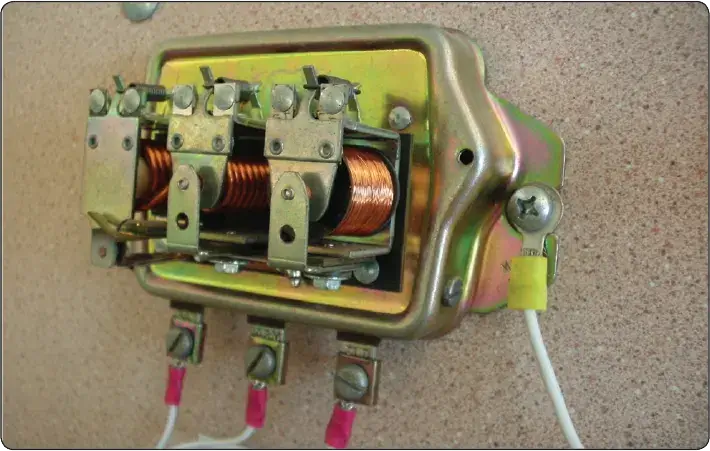 |
| Figure 6. The three relays found on this regulator are used to regulate voltage, limit current, and prevent reverse current flow |
Voltage Regulator
The voltage regulator section of the three-unit regulator is used to control generator output voltage. The voltage regulator monitors generator output and controls the generator field current as needed. If the regulator senses that system voltage is too high, the relay points open and the current in the field circuit must travel through a resistor. This resistor lowers field current and therefore lowers generator output. Remember, generator output goes down whenever generator field current goes down.
 |
| Figure 7. Voltage regulator |
As seen in Figure 7, the voltage coil is connected in parallel with the generator output, and it therefore measures the voltage of the system. If voltage gets beyond a predetermined limit, the voltage coil becomes a strong magnet and opens the contact points. If the contact points are open, field current must travel through a resistor and therefore field current goes down. The dotted arrow shows the current flow through the voltage regulator when the relay points are open.
Since this voltage regulator has only two positions (points open and points closed), the unit must constantly be in adjustment to maintain accurate voltage control. During normal system operation, the points are opening and closing at regular intervals. The points are in effect vibrating. This type of regulator is sometimes referred to as a vibrating type regulator. As the points vibrate, the field current raises and lowers and the field magnetism averages to a level that maintains the correct generator output voltage. If the system requires more generator output, the points remain closed longer and vice versa.
Current Limiter
The current limiter section of the three-unit regulator is designed to limit generator output current. This unit contains a relay with a coil wired in series with respect to the generator output. As seen in Figure 8, all the generator output current must travel through the current coil of the relay. This creates a relay that is sensitive to the current output of the generator. That is, if generator output current increases, the relay points open and vice versa. The dotted line shows the current flow to the generator field when the current limiter points are open. It should be noted that, unlike the voltage regulator relay, the current limiter is typically closed during normal flight. Only during extreme current loads must the current limiter points open; at that time, field current is lowered and generator output is kept within limits.
 |
| Figure 8. Current limiter |
Reverse-Current Relay
The third unit of a three-unit regulator is used to prevent current from leaving the battery and feeding the generator. This type of current flow would discharge the battery and is opposite to normal operation. It can be thought of as a reverse current situation and is known as reverse-current relay. The simple reverse current relay shown in Figure 9 contains both a voltage coil and a current coil.
 |
| Figure 9. Reverse-current relay |
The voltage coil is wired in parallel to the generator output and is energized any time the generator output reaches its operational voltage. As the voltage coil is energized, the contact points close and the current is then allowed to flow to the aircraft electrical loads, as shown by the dotted lines. The diagram shows the reverse current relay in its normal operating position; the points are closed and current is flowing from the generator to the aircraft electrical loads. As current flows to the loads, the current coil is energized and the points remain closed. If there is no generator output due to a system failure, the contact points open because magnetism in the relay is lost. With the contact points open, the generator is automatically disconnected from the aircraft electrical system, which prevents reverse flow from the load bus to the generator. A typical three-unit regulator for aircraft generators is shown in Figure 10.
 |
| Figure 10. Three-unit regulator for variable speed generators |
As seen in Figure 10, all three units of the regulator work together to control generator output. The regulator monitors generator output and controls power to the aircraft loads as needed for flight variables. Note that the vibrating regulator described here is simplified for explanation purposes. A typical vibrating regulator found on an aircraft would probably be more complex.
What is the primary method used to adjust a DC generator's output?
What does a Reverse-Current Relay do in a three-unit regulator?
How does a carbon pile regulator control voltage?
Why do starter-generators require a more complex control unit?
RELATED POSTS