DC generators transform mechanical energy into electrical energy. As the name implies, DC generators produce direct current and are typically found on light aircraft. In many cases, DC generators have been replaced with DC alternators. Both devices produce electrical energy to power the aircraft’s electrical loads and charge the aircraft’s battery. Even though they share the same purpose, the DC alternator and DC generator are very different. DC generators require a control circuit in order to ensure the generator maintains the correct voltage and current for the current electrical conditions of the aircraft. Typically, aircraft generators maintain a nominal output voltage of approximately 14 volts or 28 volts.
Generators
The principles of electromagnetic induction were discussed in the Electromagnetic Generation of Power post. These principles show that voltage is induced in the armature of a generator throughout the entire 360° rotation of the conductor. The armature is the rotating portion of a DC generator. As shown, the voltage being induced is AC. [Figure 1]
 |
| Figure 1. Output of an elementary generator |
Since the conductor loop is constantly rotating, some means must be provided to connect this loop of wire to the electrical loads. As shown in Figure 2, slip rings and brushes can be used to transfer the electrical energy from the rotating loop to the stationary aircraft loads. The slip rings are connected to the loop and rotate; the brushes are stationary and allow a current path to the electrical loads. The slip rings are typically made of copper and the brushes are a soft carbon substance.
 |
| Figure 2. Generator slip rings and loop rotate; brushes are stationary |
It is important to remember that the voltage being produced by this basic generator is AC, and AC voltage is supplied to the slip rings. Since the goal is to supply DC loads, some means must be provided to change the AC voltage to a DC voltage. Generators use a modified slip ring arrangement, known as a commutator, to change the AC produced in the generator loop into a DC voltage. The action of the commutator allows the generator to produce a DC output.
By replacing the slip rings of the basic AC generator with two half-cylinders (the commutator), a basic DC generator is obtained. In Figure 3, the red side of the coil is connected to the red segment and the amber side of the coil to the amber segment. The segments are insulated from each other. The two stationary brushes are placed on opposite sides of the commutator and are so mounted that each brush contacts each segment of the commutator as the commutator revolves simultaneously with the loop. The rotating parts of a DC generator (coil and commutator) are called an armature.
 |
| Figure 3. A two-piece slip ring, or commutator, allows brushes to transfer current that flows in a single direction (DC) |
As seen in the very simple generator of Figure 3, as the loop rotates the brushes make contact with different segments of the commutator. In positions A, C, and E, the brushes touch the insulation between the commutator segments; when the loop is in these positions, no voltage is being produced. In position B, the positive brush touches the red side of the conductor loop. In position D, the positive brush touches the amber side of the armature conductor. This type of connection reversal changes the AC produced in the conductor coil into DC to power the aircraft. An actual DC generator is more complex, having several loops of wire and commutator segments.
Because of this switching of commutator elements, the red brush is always in contact with the coil side moving downward, and the amber brush is always in contact with the coil side moving upward. Though the current actually reverses its direction in the loop in exactly the same way as in the AC generator, commutator action causes the current to flow always in the same direction through the external circuit or meter.
The voltage generated by the basic DC generator in Figure 3 varies from zero to its maximum value twice for each revolution of the loop. This variation of DC voltage is called ripple and may be reduced by using more loops, or coils, as shown in Figure 4.
 |
| Figure 4. Increasing the number of coils reduces the ripple in the voltage |
As the number of loops is increased, the variation between maximum and minimum values of voltage is reduced [Figure 4], and the output voltage of the generator approaches a steady DC value. For each additional loop in the rotor, two additional commutator segments are required. A photo of a typical DC generator commutator is shown in Figure 5.
 |
| Figure 5. Typical DC generator commutator |
Construction Features of DC Generators
The major parts, or assemblies, of a DC generator are a field frame, a rotating armature, and a brush assembly. The parts of a typical aircraft generator are shown in Figure 6.
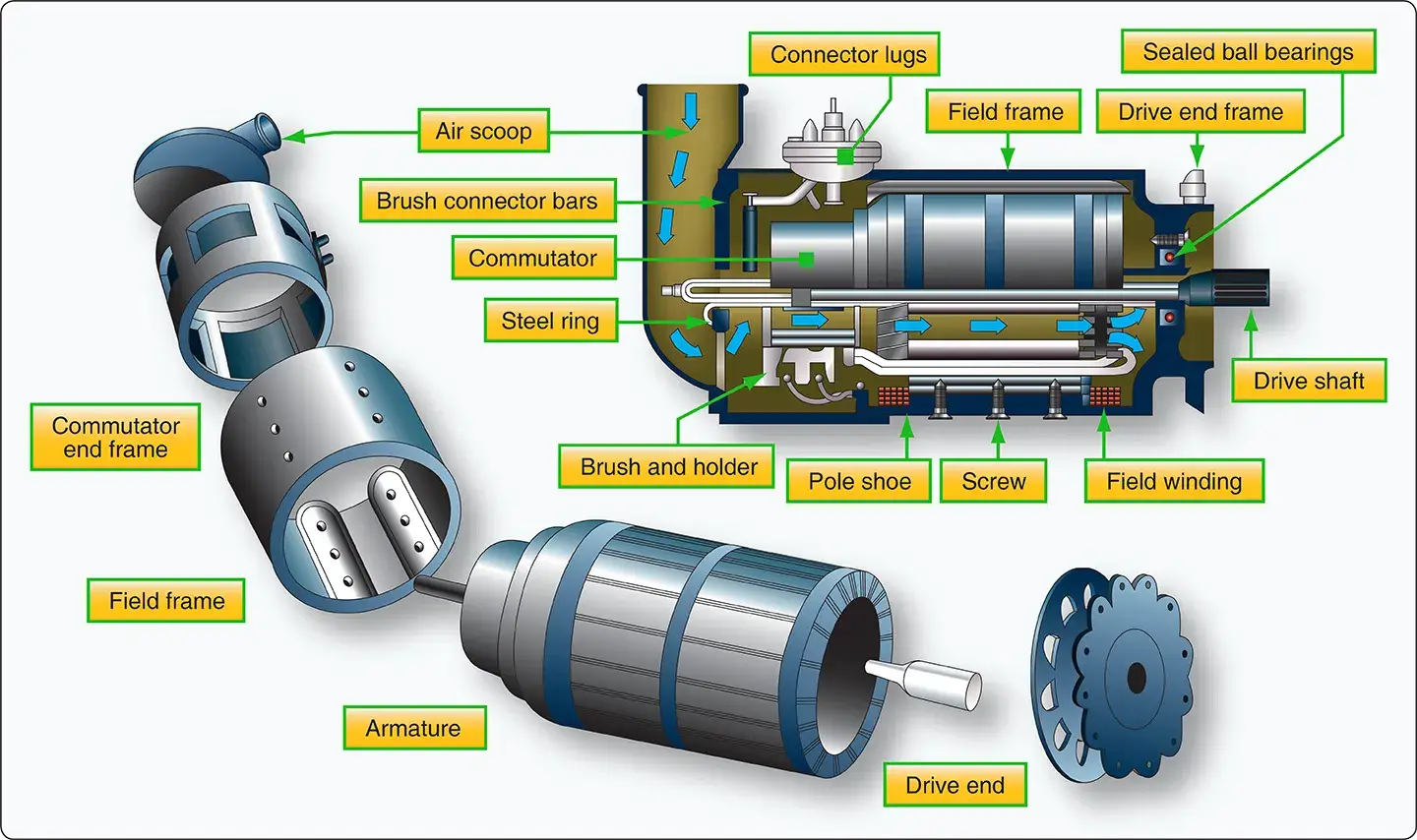 |
| Figure 6. Typical 24-volt aircraft generator |
Field Frame
The frame has two functions: to hold the windings needed to produce a magnetic field, and to act as a mechanical support for the other parts of the generator. The actual electromagnet conductor is wrapped around pieces of laminated metal called field poles. The poles are typically bolted to the inside of the frame and laminated to reduce eddy current losses and serve the same purpose as the iron core of an electromagnet; they concentrate the lines of force produced by the field coils. The field coils are made up of many turns of insulated wire and are usually wound on a form that fits over the iron core of the pole to which it is securely fastened. [Figure 7]
 |
| Figure 7. Generator field frame |
A DC current is fed to the field coils to produce an electromagnetic field. This current is typically obtained from an external source that provides voltage and current regulation for the generator system.
Armature
The armature assembly of a generator consists of two primary elements: the wire coils (called windings) wound around an iron core and the commutator assembly. The armature windings are evenly spaced around the armature and mounted on a steel shaft. The armature rotates inside the magnetic field produced by the field coils. The core of the armature acts as an iron conductor in the magnetic field and, for this reason, is laminated to prevent the circulation of eddy currents. A typical armature assembly is shown in Figure 8.
 |
| Figure 8. A drum-type armature |
Commutators
Figure 9 shows a cross-sectional view of a typical commutator. The commutator is located at the end of an armature and consists of copper segments divided by a thin insulator. The insulator is often made from the mineral mica. The brushes ride on the surface of the commutator forming the electrical contact between the armature coils and the external circuit. A flexible, braided copper conductor, commonly called a pigtail, connects each brush to the external circuit. The brushes are free to slide up and down in their holders in order to follow any irregularities in the surface of the commutator. The constant making and breaking of electrical connections between the brushes and the commutator segments, along with the friction between the commutator and the brush, causes brushes to wear out and need regular attention or replacement. For these reasons, the material commonly used for brushes is high-grade carbon. The carbon must be soft enough to prevent undue wear of the commutator and yet hard enough to provide reasonable brush life. Since the contact resistance of carbon is fairly high, the brush must be relatively large to provide a current path for the armature windings.
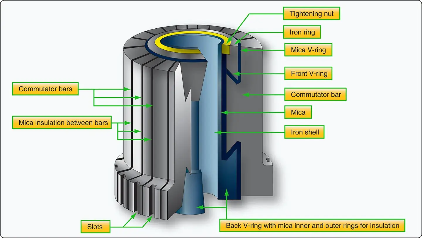 |
| Figure 9. Commutator with portion removed to show construction |
The commutator surface is highly polished to reduce friction as much as possible. Oil or grease must never be used on a commutator, and extreme care must be used when cleaning it to avoid marring or scratching the surface.
Types of DC Generators
There are three types of DC generators: series wound, parallel (shunt) wound, and series-parallel (compound wound). The appropriate generator is determined by the connections to the armature and field circuits with respect to the external circuit. The external circuit is the electrical load powered by the generator. In general, the external circuit is used for charging the aircraft battery and supplying power to all electrical equipment being used by the aircraft. As their names imply, windings in series have characteristics different from windings in parallel.
Series Wound DC Generators
The series generator contains a field winding connected in series with the external circuit. [Figure 10] Series generators have very poor voltage regulation under changing load, since the greater the current is through the field coils to the external circuit, the greater the induced EMFs and the greater the output voltage is. When the aircraft electrical load is increased, the voltage increases; when the load is decreased, the voltage decreases.
 |
| Figure 10. Diagram of a series wound generator |
Since the series wound generator has such poor voltage and current regulation, it is never employed as an airplane generator. Generators in airplanes have field windings, that are connected either in shunt or in compound formats.
Parallel (Shunt) Wound DC Generators
A generator having a field winding connected in parallel with the external circuit is called a shunt generator. [Figure 11] It should be noted that, in electrical terms, shunt means parallel. Therefore, this type of generator could be called either a shunt generator or a parallel generator.
 |
| Figure 11. Shunt wound generator |
In a shunt generator, any increase in load causes a decrease in the output voltage, and any decrease in load causes an increase in output voltage. This occurs since the field winding is connected in parallel to the load and armature, and all the current flowing in the external circuit passes only through the armature winding (not the field).
As shown in Figure 11A, the output voltage of a shunt generator can be controlled by means of a rheostat inserted in series with the field windings. As the resistance of the field circuit is increased, the field current is reduced; consequently, the generated voltage is also reduced. As the field resistance is decreased, the field current increases and the generator output increases. In the actual aircraft, the field rheostat would be replaced with an automatic control device, such as a voltage regulator.
Compound Wound DC Generators
A compound wound generator employs two field windings, one in series and another in parallel with the load. [Figure 12] This arrangement takes advantage of both the series and parallel characteristics described earlier. The output of a compound wound generator is relatively constant, even with changes in the load.
 |
| Figure 12. Compound wound generator |
Generator Ratings
A DC generator is typically rated for its voltage and power output. Each generator is designed to operate at a specified voltage, approximately 14 or 28 volts. It should be noted that aircraft electrical systems are designed to operate at one of these two voltage values. The aircraft’s voltage depends on which battery is selected for that aircraft. Batteries are either 12 or 24 volts when fully charged. The generator selected must have a voltage output slightly higher than the battery voltage. Hence, the 14- or 28-volt rating is required for aircraft DC generators.
The power output of any generator is specified as the maximum current (in amperes) the generator can safely supply. Generator rating and performance data are stamped on the nameplate attached to the generator. When replacing a generator, it is important to select a generator with the correct rating.
The rotation of generators is termed either clockwise or counterclockwise, as viewed from the driven end. The direction of rotation may also be stamped on the data plate. It is important that a generator with the correct rotation be used; otherwise, the polarity of the output voltage is reversed. The speed of an aircraft engine varies from idle rpm to takeoff rpm; however, during the major portion of a flight, it is at a constant cruising speed. The generator drive is usually geared to turn the generator between 1⅛ to 1½ times the engine crankshaft speed. Most aircraft generators have a speed at which they begin to produce their normal voltage. Called the “coming in” speed, it is usually about 1,500 rpm.
DC Generator Maintenance
The following information about the inspection and maintenance of DC generator systems is general in nature because of the large number of differing aircraft generator systems. These procedures are for familiarization only. Always follow the applicable manufacturer’s instructions for a given generator system. In general, the inspection of the generator installed in the aircraft should include the following items:
- Security of generator mounting.
- Condition of electrical connections.
- Dirt and oil in the generator. If oil is present, check engine oil seals. Blow out any dirt with compressed air.
- Condition of generator brushes.
- Generator operation.
- Voltage regulator operation.
Sparking of brushes quickly reduces the effective brush area in contact with the commutator bars. The degree of such sparking should be determined. Excessive wear warrants a detailed inspection and possible replacement of various components. [Figure 13]
 |
| Figure 13. Wear areas of commutator and brushes |
Manufacturers usually recommend the following procedures to seat brushes that do not make good contact with slip rings or commutators. Lift the brush sufficiently to permit the insertion of a strip of extra-fine 000 (triple aught) grit, or finer, sandpaper under the brush, rough side towards the carbon brush. [Figure 14]
 |
| Figure 14. Seating brushes with sandpaper |
Pull the sandpaper in the direction of armature rotation, being careful to keep the ends of the sandpaper as close to the slip ring or commutator surface as possible in order to avoid rounding the edges of the brush. When pulling the sandpaper back to the starting point, raise the brush so it does not ride on the sandpaper. Sand the brush only in the direction of rotation. Carbon dust resulting from brush sanding should be thoroughly cleaned from all parts of the generators after a sanding operation.
After the generator has run for a short period, brushes should be inspected to make sure that pieces of sand have not become embedded in the brush. Under no circumstances should emery cloth or similar abrasives be used for seating brushes (or smoothing commutators), since they contain conductive materials that cause arcing between brushes and commutator bars. It is important that the brush spring pressure is correct. Excessive pressure causes rapid wear of brushes. Too little pressure, however, allows bouncing of the brushes, resulting in burned and pitted surfaces. The pressure recommended by the manufacturer should be checked by the use of a spring scale graduated in ounces. Brush spring tension on some generators can be adjusted. A spring scale is used to measure the pressure that a brush exerts on the commutator.
Flexible low-resistance pigtails are provided on most heavy current carrying brushes, and their connections should be securely made and checked at frequent intervals. The pigtails should never be permitted to alter or restrict the free motion of the brush. The purpose of the pigtail is to conduct the current from the armature, through the brushes, to the external circuit of the generator.
What is the function of the commutator in a DC generator?
What are the three types of DC generators and which is used in aircraft?
Why is "coming in" speed important for a generator?
How do you properly seat new carbon brushes?
RELATED POSTS