Gyroscopic instruments require reliable power sources to maintain accurate attitude and directional information during flight.
Gyroscopic instruments are essential for aircraft operation. They provide the pilot with critical attitude and directional information and are particularly important during IFR flight. The sources of power for these instruments can vary. The main requirement is to spin the gyroscopes at high speed. Originally, gyroscopic instruments were strictly vacuum driven. A vacuum source pulled air across the gyro inside the instruments to make the gyros spin. Later, electricity was added as a source of power. The turning armature of an electric motor doubles as the gyro rotor. In some aircraft, pressure, rather than vacuum, is used to induce the gyro to spin. Various systems and powering configurations have been developed to provide reliable operation of the gyroscopic instruments.
Vacuum Systems
Vacuum systems are very common for driving gyro instruments. In a vacuum system, a stream of air directed against the rotor vanes turns the rotor at high speed. The action is similar to a water wheel. Air at atmospheric pressure is first drawn through a filter(s). It is then routed into the instrument and directed at vanes on the gyro rotor. A suction line leads from the instrument case to the vacuum source. From there, the air is vented overboard. Either a venturi or a vacuum pump can be used to provide the vacuum required to spin the rotors of the gyro instruments.
The vacuum value required for instrument operation is usually between 3½ to 4½ inches of mercury. It is usually adjusted by a vacuum relief valve located in the supply line. Some turn-and-bank indicators require a lower vacuum setting. This can be obtained through the use of an additional regulating valve in the turn-and-bank vacuum supply line.
Venturi Tube Systems
The velocity of the air rushing through a venturi can create sufficient suction to spin instrument gyros. A line is run from the gyro instruments to the throat of the venturi mounted on the outside of the airframe. The low pressure in the venturi tube pulls air through the instruments, spins the gyros, and expels the air overboard through the venturi. This source of gyro power is used on many simple, early aircraft.
A light, single-engine aircraft can be equipped with a 2-inch venturi (2 inches Hg vacuum capacity) to operate the turn and bank indicator. It can also have a larger 8-inch venturi to power the attitude and heading indicators. Simplified illustrations of these venturi vacuum systems are shown in Figure 1. Normally, air going into the instruments is filtered.
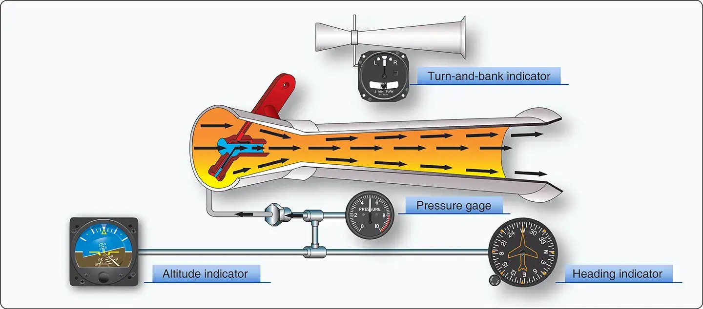 |
| Figure 1. Simple venturi tube systems for powering gyroscopic instruments |
The advantages of a venturi as a suction source are its relatively low cost and its simplicity of installation and operation. It also requires no electric power. But there are serious limitations. A venturi is designed to produce the desired vacuum at approximately 100 mph at standard sea level conditions. Wide variations in airspeed or air density cause the suction developed to fluctuate. Airflow can also be hampered by ice that can form on the venturi tube. Additionally, since the rotor does not reach normal operating speed until after takeoff, preflight operational checks of venturi powered gyro instruments cannot be made. For these reasons, alternate sources of vacuum power were developed.
Engine-Driven Vacuum Pump
The vane-type engine-driven pump is the most common source of vacuum for gyros installed in general aviation, light aircraft. One type of engine-driven pump is geared to the engine and is connected to the lubricating system to seal, cool, and lubricate the pump. Another commonly used pump is a dry vacuum pump. It operates without external lubrication and installation requires no connection to the engine oil supply. It also does not need the air oil separator or gate check valve found in wet pump systems. In many other respects, the dry pump system and oil lubricated system are the same. [Figure 2]
 |
| Figure 2. Cutaway view of a vane-type engine-driven vacuum pump used to power gyroscopic instruments |
When a vacuum pump develops a vacuum (negative pressure), it also creates a positive pressure at the outlet of the pump. This pressure is compressed air. Sometimes, it is utilized to operate pressure gyro instruments. The components for pressure systems are much the same as those for a vacuum system as listed below. Other times, the pressure developed by the vacuum pump is used to inflate de-ice boots or inflatable seals or it is vented overboard.
An advantage of engine-driven pumps is their consistent performance on the ground and in flight. Even at low engine rpm, they can produce more than enough vacuum so that a regulator in the system is needed to continuously provide the correct suction to the vacuum instruments. As long as the engine operates, the relatively simple vacuum system adequately spins the instrument gyros for accurate indications. However, engine failure, especially on single-engine aircraft, could leave the pilot without attitude and directional information at a critical time. To thwart this shortcoming, often the turn and bank indicator operates with an electrically driven gyro that can be driven by the battery for a short time. Thus, when combined with the aircraft’s magnetic compass, sufficient attitude and directional information is still available.
Multi-engine aircraft typically contain independent vacuum systems for the pilot and copilot instruments driven by separate vacuum pumps on each of the engines. Should an engine fail, the vacuum system driven by the still operating engine supplies a full complement of gyro instruments. An interconnect valve may also be installed to connect the failed instruments to the still operational pump.
Typical Pump-Driven System
The following components are found in a typical vacuum system for gyroscopic power supply. A brief description is given of each. Refer to the figures for detailed illustrations.
Air-oil separator - oil and air in the vacuum pump are exhausted through the separator, which separates the oil from the air; the air is vented overboard and the oil is returned to the engine sump. This component is not present when a dry-type vacuum pump is used. The self-lubricating nature of the pump vanes requires no oil.
Vacuum regulator or suction relief valve - since the system capacity is more than is needed for operation of the instruments, the adjustable vacuum regulator is set for the vacuum desired for the instruments. Excess suction in the instrument lines is reduced when the spring-loaded valve opens to atmospheric pressure. [Figure 3]
 |
| Figure 3. A vacuum regulator, also known as a suction relief valve, includes a foam filter. To relieve vacuum, outside air of a higher pressure must be drawn into the system. This air must be clean to prevent damage to the pump |
Gate check valve - prevents possible damage to the instruments by engine backfire that would reverse the flow of air and oil from the pump. [Figure 4]
 |
| Figure 4. Gate check valve used to prevent vacuum system damage from engine backfire |
Pressure relief valve—since a reverse flow of air from the pump would close both the gate check valve and the suction relief valve, the resulting pressure could rupture the lines. The pressure relief valve vents positive pressure into the atmosphere.
Selector valve - In twin-engine aircraft having vacuum pumps driven by both engines, the alternate pump can be selected to provide vacuum in the event of either engine or pump failure, with a check valve incorporated to seal off the failed pump.
Restrictor valve - Since the turn needle of the turn and bank indicator operates on less vacuum than that required by the other instruments, the vacuum in the main line must be reduced for use by this instrument. An in-line restrictor valve performs this function. This valve is either a needle valve or a spring-loaded regulating valve that maintains a constant, reduced vacuum for the turn-and-bank indicator.
Air filter - A master air filter screens foreign matter from the air flowing through all the gyro instruments. It is an extremely important filter requiring regular maintenance. Clogging of the master filter reduces airflow and causes a lower reading on the suction gauge. Each instrument is also provided with individual filters. In systems with no master filter that rely only upon individual filters, clogging of a filter does not necessarily show on the suction gauge.
Suction gauge - a pressure gauge which indicates the difference between the pressure inside the system and atmospheric or cabin pressure. It is usually calibrated in inches of mercury. The desired vacuum and the minimum and maximum limits vary with gyro system design. If the desired vacuum for the attitude and heading indicators is 5 inches and the minimum is 4.6 inches, a reading below the latter value indicates that the airflow is not spinning the gyros fast enough for reliable operation. In many aircraft, the system provides a suction gauge selector valve permitting the pilot to check the vacuum at several points in the system.
Suction/vacuum pressures discussed in conjunction with the operation of vacuum systems are actually negative pressures, indicated as inches of mercury below that of atmospheric pressure. The minus sign is usually not presented, as the importance is placed on the magnitude of the vacuum developed. In relation to an absolute vacuum (0 psi or 0 in Hg), instrument vacuum systems have positive pressure.
Figure 5 shows a typical engine-driven pump vacuum system containing the above components. A pump capacity of approximately 10 in Hg at engine speeds above 1,000 rpm is normal. Pump capacity and pump size vary in different aircraft, depending on the number of gyros to be operated.
 |
| Figure 5. A typical pump-driven vacuum system for powering gyroscopic instruments |
Twin-Engine Aircraft Vacuum System Operation
Twin-engine aircraft vacuum systems are more complicated. They contain an engine-driven vacuum pump on each engine. The associated lines and components for each pump are isolated from each other and act as two independent vacuum systems. The vacuum lines are routed from each vacuum pump through a vacuum relief valve and through a check valve to the vacuum four-way selector valve. The four-way valve permits either pump to supply a vacuum manifold. From the manifold, flexible hoses connect the vacuum operated instruments into the system. To reduce the vacuum for the turn and bank indicators, needle valves are included in both lines to these units.
Lines to the artificial horizons and the directional gyro receive full vacuum. From the instruments, lines are routed to the vacuum gauge through a turn-and-bank selector valve. This valve has three positions: main, left turn and bank (T&B), and right T&B. In the main position, the vacuum gauge indicates the vacuum in the lines of the artificial horizons and directional gyro. In the other positions, the lower value of vacuum for the turn and bank indicators can be read.
A schematic of this twin-engine aircraft vacuum system is shown in Figure 6. Note the following components: two engine-driven pumps, two vacuum relief valves, two flapper type check valves, a vacuum manifold, a vacuum restrictor for each turn and bank indicator, an engine four-way selector valve, one vacuum gauge, and a turn-and-bank selector valve. Not shown are system and individual instrument filters. A drain line may also be installed at the low point in the system.
 |
| Figure 6. An example of a twin-engine instrument vacuum system |
Pressure-Driven Gyroscopic Instrument Systems
Gyroscopic instruments are finely balanced devices with jeweled bearings that must be kept clean to perform properly. When early vacuum systems were developed, only oil-lubricated pumps were available. Even with the use of air-oil separators, the pressure outputs of these pumps contain traces of oil and dirt. As a result, it was preferred to draw clean air through the gyro instruments with a vacuum system, rather than using pump output pressure that presented the risk of contamination. The development of self-lubricated dry pumps greatly reduced pressure output contaminants. This made pressure gyro systems possible.
At high altitudes, the use of pressure-driven gyros is more efficient. Pressure systems are similar to vacuum systems and make use of the same components, but they are designed for pressure instead of vacuum. Thus, a pressure regulator is used instead of a suction relief valve. Filters are still extremely important to prevent damage to the gyros. Normally, air is filtered at the inlet and outlet of the pump in a pressure gyro system.
Electrically-Driven Gyroscopic Instrument Systems
A spinning motor armature can act as a gyroscope. This is the basis for electrically driven gyroscopic instruments in which the gyro rotor spin is powered by an electric motor.
Electric gyros have the advantage of being powered by the battery for a limited time if a generator fails or an engine is lost. Since air is not sent through the gyro to spin the rotor, contamination worries are also reduced. Also, elimination of vacuum pumps, plumbing, and vacuum system components saves weight.
On many small, single-engine aircraft, electric turn-and-bank or turn coordinators are combined with vacuum-powered attitude and directional gyro instruments as a means for redundancy. The reverse is also possible. By combining both types of instruments in the instrument panel, the pilot has more options. On more complex multiengine aircraft, reliable, redundant electrical systems make use of all electric-powered gyro instruments possible.
It should be noted that electric gyro instruments have some sort of indicator on the face of the dial to show when the instrument is not receiving power. Usually, this is in the form of a red flag or mark of some sort often with the word “off” written on it.
What are the primary sources of power for gyroscopic instruments?
What is the difference between a "wet" and a "dry" vacuum pump?
Why do some aircraft have an electric Turn Coordinator but a vacuum-driven Attitude Indicator?
How does a venturi tube provide vacuum for a gyro?
RELATED POSTS