Accurate temperature measurement is essential for monitoring engine performance, environmental conditions, and system operation in aircraft.
The temperature of numerous items must be known for an aircraft to be operated properly. Engine oil, carburetor mixture, inlet air, free air, engine cylinder heads, heater ducts, and exhaust gas temperature of turbine engines are all items requiring temperature monitoring. Many other temperatures must also be known. Different types of thermometers are used to collect and present temperature information.
Non-Electric Temperature Indicators
The physical characteristics of most materials change when exposed to changes in temperature. The changes are consistent, such as the expansion or contraction of solids, liquids, and gases. The coefficient of expansion of different materials varies and it is unique to each material. Most people are familiar with the liquid mercury thermometer. As the temperature of the mercury increases, it expands up a narrow passage that has a graduated scale on it to read the temperature associated with that expansion. The mercury thermometer has no application in aviation.
A bimetallic thermometer is very useful in aviation. The temperature sensing element of a bimetallic thermometer is made of two dissimilar metal strips bonded together. Each metal expands and contracts at a different rate when temperature changes. One end of the bimetallic strip is fixed, the other end is coiled. A pointer is attached to the coiled end which is set in the instrument housing. When the bimetallic strip is heated, the two metals expand. Since their expansion rates differ and they are attached to each other, the effect is that the coiled end tries to uncoil as the one metal expands faster than the other. This moves the pointer across the dial face of the instrument. When the temperature drops, the metals contract at different rates, which tends to tighten the coil and move the pointer in the opposite direction.
Direct reading bimetallic temperature gauges are often used in light aircraft to measure free air temperature or outside air temperature (OAT). In this application, a collecting probe protrudes through the windshield of the aircraft to be exposed to the atmospheric air. The coiled end of the bimetallic strip in the instrument head is just inside the windshield where it can be read by the pilot. [Figures 1 and 2]
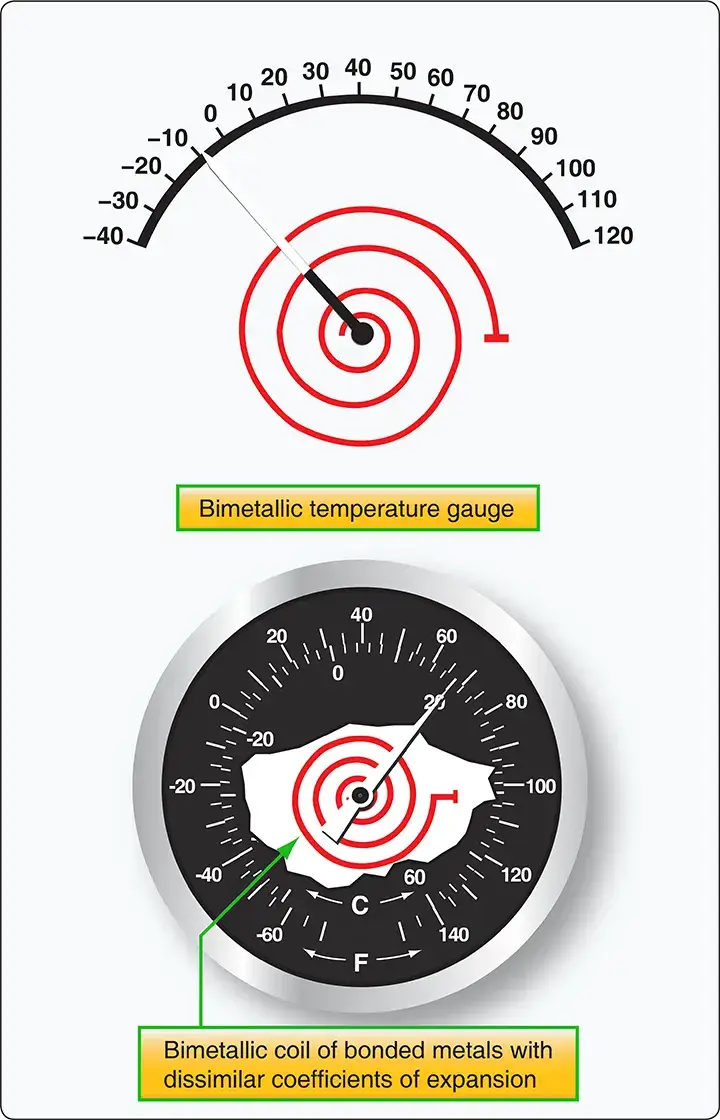 |
| Figure 1. A bimetallic temperature gauge works because of the dissimilar coefficients of expansion of two metals bonded together. When bent into a coil, cooling or heating causes the dissimilar metal coil to tighten, or unwind, moving the pointer across the temperature scale on the instrument dial face |
 |
| Figure 2. A bimetallic outside air temperature gauge and its installation on a light aircraft |
A bourdon tube is also used as a direct reading non-electric temperature gauge in simple, light aircraft. By calibrating the dial face of a bourdon tube gauge with a temperature scale, it can indicate temperature. The basis for operation is the consistent expansion of the vapor produced by a volatile liquid in an enclosed area. This vapor pressure changes directly with temperature. By filling a sensing bulb with such a volatile liquid and connecting it to a bourdon tube, the tube causes an indication of the rising and falling vapor pressure due to temperature change. Calibration of the dial face in degrees Fahrenheit or Celsius, rather than psi, provides a temperature reading. In this type of gauge, the sensing bulb is placed in the area needing to have temperature measured. A long capillary tube connects the bulb to the bourdon tube in the instrument housing. The narrow diameter of the capillary tube ensures that the volatile liquid is lightweight and stays primarily in the sensor bulb. Oil temperature is sometimes measured this way.
Electrical Temperature Measuring Indication
The use of electricity in measuring temperature is very common in aviation. The following measuring and indication systems can be found on many types of aircraft. Certain temperature ranges are more suitably measured by one or another type of system.
Electrical Resistance Thermometer
The principle parts of the electrical resistance thermometer are the indicating instrument, the temperature-sensitive element (or bulb), and the connecting wires and plug connectors. Electrical resistance thermometers are used widely in many types of aircraft to measure carburetor air, oil, free air temperatures, and more. They are used to measure low and medium temperatures in the –70 °C to 150 °C range.
For most metals, electrical resistance changes as the temperature of the metal changes. This is the principle upon which a resistance thermometer operates. Typically, the electrical resistance of a metal increases as the temperature rises. Various alloys have a high temperature-resistance coefficient, meaning their resistance varies significantly with temperature. This can make them suitable for use in temperature sensing devices. The metal resistor is subjected to the fluid or area in which temperature needs to be measured. It is connected by wires to a resistance measuring device inside the flight deck indicator. The instrument dial is calibrated in degrees Fahrenheit or Celsius as desired rather than in ohms. As the temperature to be measured changes, the resistance of the metal changes and the resistance measuring indicator shows to what extent.
A typical electrical resistance thermometer looks like any other temperature gauge. Indicators are available in dual form for use in multiengine aircraft. Most indicators are self-compensating for changes in flight deck temperature. The heat-sensitive resistor is manufactured so that it has a definite resistance for each temperature value within its working range. The temperature-sensitive resistor element is a length or winding made of a nickel/manganese wire or other suitable alloy in an insulating material. The resistor is protected by a closed-end metal tube attached to a threaded plug with a hexagonal head. [Figure 3] The two ends of the winding are brazed, or welded, to an electrical receptacle designed to receive the prongs of the connector plug.
 |
| Figure 3. An electric resistance thermometer sensing bulb |
The indicator contains a resistance-measuring instrument. Sometimes it uses a modified form of the Wheatstone-bridge circuit. The Wheatstone-bridge meter operates on the principle of balancing one unknown resistor against other known resistances. A simplified form of a Wheatstone-bridge circuit is shown in Figure 4. Three equal values of resistance [Figure 4A, B, and C] are connected into a diamond-shaped bridge circuit. A resistor with an unknown value [Figure 4D] is also part of the circuit. The unknown resistance represents the resistance of the temperature bulb of the electrical resistance thermometer system. A galvanometer is attached across the circuit at points X and Y.
 |
| Figure 4. The internal structure of an electric resistance thermometer indicator features a bridge circuit, galvanometer, and variable resistor, which is outside the indicator in the form of the temperature sensor |
When the temperature causes the resistance of the bulb to equal that of the other resistances, no potential difference exists between points X and Y in the circuit. Therefore, no current flows in the galvanometer leg of the circuit. If the temperature of the bulb changes, its resistance also changes, and the bridge becomes unbalanced, causing current to flow through the galvanometer in one direction or the other. The galvanometer pointer is actually the temperature gauge pointer. As it moves against the dial face calibrated in degrees, it indicates temperature. Many indicators are provided with a zero adjustment screw on the face of the instrument. This adjusts the zeroing spring tension of the pointer when the bridge is at the balance point (the position at which the bridge circuit is balanced and no current flows through the meter).
Ratiometer Electrical Resistance Thermometers
Another way of indicating temperature when employing an electric resistance thermometer is by using a ratiometer. The Wheatstone-bridge indicator is subject to errors from line voltage fluctuation. The ratiometer is more stable and can deliver higher accuracy. As its name suggests, the ratiometer electrical resistance thermometer measures a ratio of current flows.
The resistance bulb sensing portion of the ratiometer electric resistance thermometer is essentially the same as described above. The circuit contains a variable resistance and a fixed resistance to provide the indication. It contains two branches for current flow. Each has a coil mounted on either side of the pointer assembly that is mounted within the magnetic field of a large permanent magnet. Varying current flow through the coils causes different magnetic fields to form, which react with the larger magnetic field of the permanent magnet. This interaction rotates the pointer against the dial face that is calibrated in degrees Fahrenheit or Celsius, giving a temperature indication. [Figure 5]
 |
| Figure 5. A ratiometer temperature measuring indicator has two coils. As the sensor bulb resistance varies with temperature, different amounts of current flow through the coils. This produces varying magnetic fields. These fields interact with the magnetic field of a large permanent magnet, resulting in an indication of temperature |
The magnetic pole ends of the permanent magnet are closer at the top than they are at the bottom. This causes the magnetic field lines of flux between the poles to be more concentrated at the top. As the two coils produce their magnetic fields, the stronger field interacts and pivots downward into the weaker, less concentrated part of the permanent magnet field, while the weaker coil magnetic field shifts upward toward the more concentrated flux field of the large magnet. This provides a balancing effect that changes but stays in balance as the coil field strengths vary with temperature and the resultant current flowing through the coils.
For example, if the resistance of the temperature bulb is equal to the value of the fixed resistance (R), equal values of current flow through the coils. The torques, caused by the magnetic field each coil creates, are the same and cancel any movement in the larger magnetic field. The indicator pointer will be in the vertical position. If the bulb temperature increases, its resistance also increases. This causes the current flow through coil A circuit branch to increase. This creates a stronger magnetic field at coil A than at coil B. Consequently, the torque on coil A increases, and it is pulled downward into the weaker part of the large magnetic field. At the same time, less current flows through the sensor bulb resistor and coil B, causing coil B to form a weaker magnetic field that is pulled upward into the stronger flux area of the permanent magnet’s magnetic field. The pointer stops rotating when the fields reach a new balance point that is directly related to the resistance in the sensing bulb. The opposite of this action would take place if the temperature of the heat-sensitive bulb should decrease.
Ratiometer temperature measuring systems are used to measure engine oil, outside air, carburetor air, and other temperatures in many types of aircraft. They are especially in demand to measure temperature conditions where accuracy is important, or large variations of supply voltages are encountered.
Thermocouple Temperature Indicators
A thermocouple is a circuit or connection of two dissimilar metals. The metals are touching at two separate junctions. If one of the junctions is heated to a higher temperature than the other, an electromotive force is produced in the circuit. This voltage is directly proportional to the temperature. So, by measuring the amount of electromotive force, temperature can be determined. A voltmeter is placed across the colder of the two junctions of the thermocouple. It is calibrated in degrees Fahrenheit or Celsius, as needed. The hotter the high-temperature junction (hot junction) becomes, the greater the electromotive force produced, and the higher the temperature indication on the meter. [Figure 6]
 |
| Figure 6. Thermocouples combine two unlike metals that cause current flow when heated |
Thermocouples are used to measure high temperatures. Two common applications are the measurement of cylinder head temperature (CHT) in reciprocating engines and exhaust gas temperature (EGT) in turbine engines. Thermocouple leads are made from a variety of metals, depending on the maximum temperature to which they are exposed. Iron and constantan, or copper and constantan, are common for CHT measurement. Chromel and alumel are used for turbine EGT thermocouples.
The amount of voltage produced by the dissimilar metals when heated is measured in millivolts. Therefore, thermocouple leads are designed to provide a specific amount of resistance in the thermocouple circuit (usually very little). Their material, length, or cross-sectional size cannot be altered without compensation for the change in total resistance that would result. Each lead that makes a connection back to the voltmeter must be made of the same metal as the part of the thermocouple to which it is connected. For example, a copper wire is connected to the copper portion of the hot junction, and a constantan wire is connected to the constantan part.
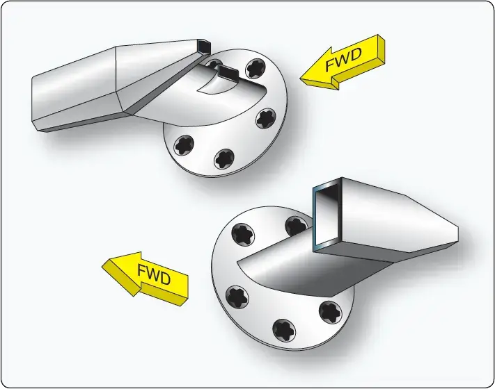
The hot junction of a thermocouple varies in shape depending on its application. Two common types are the gasket and the bayonet. In the gasket type, two rings of the dissimilar metals are pressed together to form a gasket that can be installed under a spark plug or cylinder hold down nut. In the bayonet type, the metals come together inside a perforated protective sheath. Bayonet thermocouples fit into a hole or well in a cylinder head. On turbine engines, they are found mounted on the turbine inlet or outlet case and extend through the case into the gas stream. Note that for CHT indication, the cylinder chosen for the thermocouple installation is the one that runs the hottest under most operating conditions. The location of this cylinder varies with different engines. [Figure 7]
 |
| Figure 7. A cylinder head temperature thermocouple with a gasket type hot junction is made to be installed under the spark plug or a cylinder hold down nut of the hottest cylinder (A). A bayonet type thermocouple is installed in a bore in the cylinder wall (B) |
The cold junction of the thermocouple circuit is inside the instrument case. Since the electromotive force set up in the circuit varies with the difference in temperature between the hot and cold junctions, it is necessary to compensate the indicator mechanism for changes in flight deck temperature which affect the cold junction. This is accomplished by using a bimetallic spring connected to the indicator mechanism. This actually works the same as the bimetallic thermometer described previously. When the leads are disconnected from the indicator, the temperature of the flight deck area around the instrument panel can be read on the indicator dial. [Figure 8] Numeric LED indicators for CHT are also common in modern aircraft.
 |
| Figure 8. Typical thermocouple temperature indicators |
Turbine Gas Temperature Indicating Systems
EGT is a critical variable of turbine engine operation. The EGT indicating system provides a visual temperature indication in the flight deck of the turbine exhaust gases as they leave the turbine unit. In certain turbine engines, the temperature of the exhaust gases is measured at the entrance to the turbine unit. This is referred to as a turbine inlet temperature (TIT) indicating system.
Several thermocouples are used to measure EGT or TIT. They are spaced at intervals around the perimeter of the engine turbine casing or exhaust duct. The tiny thermocouple voltages are typically amplified and used to energize a servomotor that drives the indicator pointer. Gearing a digital drum indication off of the pointer motion is common. [Figure 9]
 |
| Figure 9. A typical exhaust gas temperature thermocouple system |
The EGT indicator shown is a hermetically sealed unit. The instrument’s scale ranges from 0 °C to 1,200 °C, with a vernier dial in the upper right-hand corner and a power off warning flag located in the lower portion of the dial.
A TIT indicating system provides a visual indication at the instrument panel of the temperature of gases entering the turbine. Numerous thermocouples can be used with the average voltage representing the TIT. Dual thermocouples exist containing two electrically independent junctions within a single probe. One set of these thermocouples is paralleled to transmit signals to the flight deck indicator. The other set of parallel thermocouples provides temperature signals to engine monitoring and control systems. Each circuit is electrically independent, providing dual system reliability.
A schematic for the turbine inlet temperature system for one engine of a four-engine turbine aircraft is shown in Figure 10.
 |
| Figure 10. A typical analog turbine inlet temperature indicating system |
Circuits for the other three engines are identical to this system. The indicator contains a bridge circuit, a chopper circuit, a two-phase motor to drive the pointer, and a feedback potentiometer. Also included are a voltage reference circuit, an amplifier, a power-off flag, a power supply, and an over-temperature warning light. Output of the amplifier energizes the variable field of the two-phase motor that positions the indicator main pointer and a digital indicator. The motor also drives the feedback potentiometer to provide a feedback signal to stop the drive motor when the correct pointer position, relative to the temperature signal, has been reached. The voltage reference circuit provides a closely regulated reference voltage in the bridge circuit to preclude error from input voltage variation to the indicator power supply.
The over-temperature warning light in the indicator illuminates when the TIT reaches a predetermined limit. An external test switch is usually installed so that over-temperature warning lights for all the engines can be tested at the same time. When the test switch is operated, an over-temperature signal is simulated in each indicator temperature control bridge circuit.
Digital flight deck instrumentation systems need not employ resistance-type indicators and adjusted servo-driven thermocouple gauges to provide the pilot with temperature information. Sensor resistance and voltage values are input to the appropriate computer, where they are adjusted, processed, monitored, and output for display on flight deck display panels. They are also sent for use by other computers requiring temperature information for the control and monitoring of various integrated systems.
Total Air Temperature Measurement
Air temperature is a valuable parameter that many performance monitoring and control variables depend on. During flight, static air temperature changes continuously and accurate measurement presents challenges. Below Mach 0.2, a simple resistance-type or bimetallic temperature gauge can provide relatively accurate air temperature information. At faster speeds, friction, the air’s compressibility, and boundary layer behavior make accurate temperature capture more complex. Total air temperature (TAT) is the static air temperature plus any rise in temperature caused by the high-speed movement of the aircraft through the air. The increase in temperature is known as ram rise. TAT-sensing probes are constructed specifically to accurately capture this value and transmit signals for flight deck indication, as well as for use in various engine and aircraft systems.
Simple TAT systems include a sensor and an indicator with a built-in resistance balance circuit. Air flow through the sensor is designed so that air with the precise temperature impacts a platinum alloy resistance element. The sensor is engineered to capture temperature variations in terms of varying the resistance of the element. When placed in the bridge circuit, the indicator pointer moves in response to the imbalance caused by the variable resistor.
More complex systems use signal correction technology and amplified signals sent to a servo motor to adjust the indicator in the flight deck. These systems include closely regulated power supply and failure monitoring. They often use numeric drum type readouts but can also be sent to an LCD driver to illuminate LCD displays. Many LCD displays are multifunctional, capable of displaying static air temperature and true airspeed. In fully digital systems, the correction signals are input into the ADC. There, they can be manipulated appropriately for flight deck display or for whichever system requires temperature information. [Figure 11]
 |
| Figure 11. Different cockpit TAT displays |
TAT sensor/probe design is complicated by the potential of ice forming during icing conditions. Left unheated, a probe may cease to function properly. The inclusion of a heating element threatens accurate data collection. Heating the probe must not affect the resistance of the sensor element. [Figure 12]
 |
| Figure 12. Total air temperature (TAT) probes |
Close attention is paid to airflow and materials conductivity during the design phase. Some TAT sensors channel bleed air through the units to affect the flow of outside air, so that airflow reaches the platinum sensor directly without gaining added energy from the probe heater.
What is the difference between an electrical resistance thermometer and a thermocouple?
How does a bimetallic thermometer measure Outside Air Temperature (OAT)?
What is "Total Air Temperature" (TAT) and why is it important?
Why is a Wheatstone Bridge or Ratiometer used in temperature gauges?
RELATED POSTS