Mechanical movement indicators provide essential information about engine performance, aircraft motion, and aerodynamic conditions during flight.
There are many instruments on an aircraft that indicate the mechanical motion of a component, or even the aircraft itself. Some utilize synchro remote-sensing and indicating systems. Other means for capturing and displaying mechanical movement information are also used. This post discusses some unique mechanical motion indicators and groups instruments by function. All give valuable feedback to the pilot on the condition of the aircraft in flight.
Tachometers
The tachometer, or tach, is an instrument that indicates the speed of the crankshaft of a reciprocating engine. It can be a direct- or remote-indicating instrument, the dial of which is calibrated to indicate revolutions per minute (rpm). On reciprocating engines, the tach is used to monitor engine power and to ensure the engine is operated within certified limits.
Gas turbine engines also have tachometers. They are used to monitor the speed(s) of the compressor section(s) of the engine. Turbine engine tachometers are calibrated in percentage of rpm with 100 percent corresponding to optimum turbine speed. This allows similar operating procedures despite the varied actual engine rpm of different engines. [Figure 1]
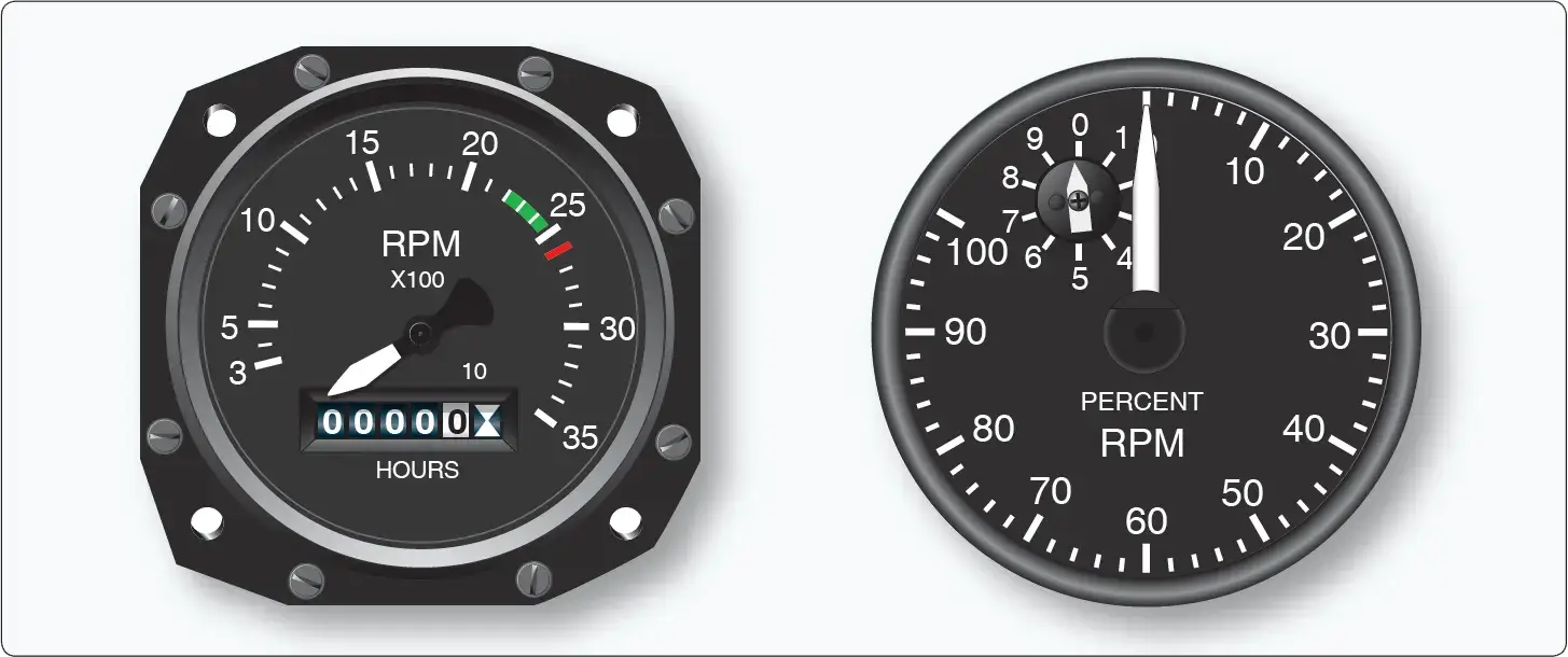 |
| Figure 1. A tachometer for a reciprocating engine is calibrated in rpm. A tachometer for a turbine engine is calculated in percent of rpm |
In addition to the engine tachometer, helicopters use a tachometer to indicate main rotor shaft rpm. It should also be noted that many reciprocating-engine tachometers also have built-in numeric drums that are geared to the rotational mechanism inside. These are hour meters that keep track of the time the engine is operated. There are two types of tachometer system in wide use today: mechanical and electrical.
Mechanical Tachometers
Mechanical tachometer indicating systems are found on small, single-engine light aircraft in which a short distance exists between the engine and the instrument panel. They consist of an indicator connected to the engine by a flexible drive shaft. The drive shaft is geared into the engine so that when the engine turns, so does the shaft. The indicator contains a flyweight assembly coupled to a gear mechanism that drives a pointer. As the drive shaft rotates, centrifugal force acts on the flyweights and moves them to an angular position. This angular position varies with the rpm of the engine. The amount of movement of the flyweights is transmitted through the gear mechanism to the pointer. The pointer rotates to indicate this movement on the tachometer indicator, which is directly related to the rpm of the engine. [Figure 2]
 |
| Figure 2. The simplified mechanism of a flyweight type mechanical tachometer |
A more common variation of this type of mechanical tachometer uses a magnetic drag cup to move the pointer in the indicator. As the drive shaft turns, it rotates a permanent magnet in a close-tolerance aluminum cup. A shaft attached to the indicating pointer is attached to the exterior center of the cup. As the magnet is rotated by the engine flex drive cable, its magnetic field cuts through the conductor surrounding it, creating eddy currents in the aluminum cup. This current flow creates its own magnetic field, which interacts with the rotating magnet’s flux field. The result is that the cup tends to rotate, and with it, the indicating pointer. A calibrated restraining spring limits the cup’s rotation to the arc of motion of the pointer across the scale on the instrument face. [Figure 3]
 |
| Figure 3. A simplified magnetic drag cup tachometer indicating device |
A popular electric tachometer system makes use of a small AC generator mounted on a reciprocating engine’s gear case or the accessory drive section of a turbine engine. As the engine turns, so does the generator. The frequency output of the generator is directly proportional to the speed of the engine. It is connected via wires to a synchronous motor in the indicator that mirrors this output. A drag cup, or drag disk link, is used to drive the indicator as in a mechanical tachometer. [Figure 4]
 |
| Figure 4. An electric tachometer system with synchronous motors and a drag cup indicator |
Two different types of generator units, distinguished by their type of mounting system, are shown in Figure 5.
 |
| Figure 5. Different types of tach generators |
The dual tachometer consists of two tachometer indicator units housed in a single case. The indicator pointers show simultaneously on one or two scales, the rpm of two engines. A dual tachometer on a helicopter often shows the rpm of the engine and the rpm of the main rotor. A comparison of the voltages produced by the two tach generators of this type of helicopter indicator gives information concerning clutch slippage. A third indication showing this slippage is sometimes included in the helicopter tachometer. [Figure 6]
 |
| Figure 6. A helicopter tachometer with engine rpm, rotor rpm, and slippage indications |
Some turbine engines use tachometer probes for rpm indication, rather than a tach generator system. They provide a great advantage in that there are no moving parts. The probes are sealed units that are mounted on a flange and protrude into the compressor section of the engine. A magnetic field is set up inside the probe that extends through pole pieces and out the end of the probe. A rotating gear wheel, which moves at the same speed as the engine compressor shaft, alters the magnetic field flux density as it moves past the pole pieces at close proximity. This generates voltage signals in coils inside the probe. The amplitude (voltage) of the signals varies directly with the speed of the engine.
The tachometer probe’s output signals need to be processed in a remotely located module. They must also be amplified to drive a servo motor type indicator in the flight deck. They may also be used as input for an autothrottle or flight data acquisition system. [Figure 7]
 |
| Figure 7. A tacho probe has no moving parts. The rate of magnetic flux field density change is directly related to engine speed |
Synchroscope
The synchroscope is an instrument that indicates whether two or more rotating devices, such as engines, are synchronized. Since synchroscopes compare rpm, they utilize the output from tachometer generators. The instrument consists of a small electric motor that receives electrical current from the generators of both engines. Current from the faster running engine controls the direction in which the synchroscope motor rotates.
If both engines are operating at exactly the same speed, the synchroscope motor does not operate. If one engine operates faster than the other, its tach generator signal causes the synchroscope motor to turn in a given direction. Should the speed of the other engine then become greater than that of the first engine, the signal from its tach generator causes the synchroscope motor to reverse itself and turn in the opposite direction. The pilot makes adjustments to steady the pointer so it does not move.
 |
| Figure 8. This synchroscope indicates the relative speed of the slave engine to the master |
One use of synchroscope involves designating one of the engines as a master engine. The rpm of the other engine(s) is always compared to the rpm of this master engine. The dial face of the synchroscope indicator looks like Figure 8. “Slow” and “fast” represent the other engine’s rpm relative to the master engine, and the pilot makes adjustments accordingly.
Accelerometers
An accelerometer is an instrument that measures acceleration. It is used to monitor the forces acting upon an airframe. Accelerometers are also used in inertial reference navigation systems. The installation of accelerometers is usually limited to high-performance and aerobatic aircraft.
Simple accelerometers are mechanical, direct-reading instruments calibrated to indicate force in Gs (g-forces). One G is equal to one times the force of gravity. The dial face of an accelerometer is scaled to show positive and negative forces. When an aircraft initiates a rapid climb, positive G force tends to push the pilot back into the seat. Initiating a rapid descent causes a force in the opposite direction, resulting in a negative G force.
Most accelerometers have three pointers. One is continuously indicating the acceleration force experienced. The other two contain ratcheting devices. The positive G pointer follows the continuous pointer and stay at the location on the dial where the maximum positive force is indicated. The negative G pointer does the same for negative forces experienced. Both max force pointers can be reset with a knob on the instrument face.
 |
| Figure 9. The inner workings of a mass-type accelerometer |
The accelerometer operates on the principle of inertia. A mass, or weight, inside is free to slide along a shaft in response to the slightest acceleration force. When a maneuver creates an accelerating force, the aircraft and instrument move, but inertia causes the weight to stay at rest in space. As the shaft slides through the weight, the relative position of the weight on the shaft changes. This position corresponds to the force experienced. Through a series of pulleys, springs, and shafts, the pointers are moved on the dial to indicate the relative strength of the acceleration force. [Figure 9]
Forces can act upon an airframe along the three axes of flight. Single and multi-axis accelerometers are available, although most cockpit gauges are of the single-axis type. Inertial reference navigation systems make use of multi-axis accelerometers to continuously, mathematically calculate the location of the aircraft in a three-dimensional plane.
Electric and digital accelerometers also exist. Solid-state sensors are employed, such as piezoelectric crystalline devices. In these instruments, when an accelerating force is applied, the amount of resistance, current flow, or capacitance changes in direct relationship to the size of the force. Microelectric signals integrate well with digital computers designed to process and display information in the flight deck.
Stall Warning and Angle of Attack (AOA) Indicators
An aircraft’s angle of attack (AOA) is the angle formed between the wing chord centerline and the relative wind. At a certain angle, airflow over the wing surfaces is insufficient to create enough lift to keep the aircraft flying, and a stall occurs. An instrument that monitors the AOA allows the pilot to avoid such a condition.
The simplest form of AOA indicator is a stall warning device that does not have a gauge located in the flight deck. It uses an aural tone to warn of an impending stall due to an increase in AOA. This is done by placing a reed in a cavity just aft of the leading edge of the wing. The cavity has an open passage to a precise point on the leading edge.
In flight, air flows over and under a wing. The point on the wing leading edge where the oncoming air diverges is known as the point of stagnation. As the AOA of the wing increases, the point of stagnation moves down below the open passage that leads inside the wing to the reed. Air flowing over the curved leading edge speeds up and causes a low pressure. This causes air to be sucked out of the inside of the wing through the passage. The reed vibrates as the air rushes by making a sound audible in the flight deck. [Figure 10]
 |
| Figure 10. A reed-type stall warning device is located behind this opening in the leading edge of the wing. When the angle of attack increases to near the point of a stall, low-pressure air flowing over the opening causes a suction, which audibly vibrates the reed |
Another common device makes use of an audible tone as the AOA increases to near the point where the aircraft will stall. This stall warning device includes an electric switch that opens and closes a circuit to a warning horn audible in the flight deck. It may also be wired into a warning light circuit. The switch is located near the point of stagnation on the wing leading edge. A small lightly sprung tab activates the switch. At normal AOA, the tab is held down by air that diverges at the point of stagnation and flows under the wing. This holds the switch open so the horn does not sound nor the warning light illuminate. As the AOA increases, the point of stagnation moves down. The divergent air that flows up and over the wing now pushes the tab upward to close the switch and complete the circuit to the horn or light. [Figure 11]
 |
| Figure 11. A popular stall warning switch located in the wing leading edge |
A true AOA indicating system detects the local AOA of the aircraft and displays the information on a flight deck indicator. It also may be designed to furnish reference information to other systems on high-performance aircraft. The sensing mechanism and transmitter are usually located on the forward side of the fuselage. It typically contains a heating element to ensure ice-free operation. Signals are sent from the sensor to the flight deck or computer(s) as required. An AOA indicator may be calibrated in actual angle degrees, arbitrary units, percentage of lift used, symbols, or even fast/slow. [Figure 12]
 |
| Figure 12. Angle of attack indicator |
There are two main types of AOA sensors in common use. Both detect the angular difference between the relative wind and the fuselage, which is used as a reference plane. One uses a vane, known as an alpha vane, externally mounted to the outside of the fuselage. It is free to rotate in the wind. As the AOA changes, air flowing over the vane changes its angle. The other uses two slots in a probe that extends out of the side of the fuselage into the airflow. The slots lead to different sides of movable paddles in a chamber of the unit just inside the fuselage skin. As the AOA varies, the air pressure ported by each of the slots changes and the paddles rotate to neutralize the pressures. The shaft upon which the paddles rotate connects to a potentiometer wiper contact that is part of the unit. The same is true of the shaft of the alpha vane. The changing resistance of the potentiometer is used in a balanced bridge circuit to signal a motor in the indicator to move the pointer proportional to the AOA. [Figures 13 and 14]
 |
| Figure 13. A slotted AOA probe and an alpha vane |
 |
| Figure 14. The internal structure of a slotted probe airstream direction detector |
Modern aircraft AOA sensor units send output signals to the ADC. There, the AOA data is used to create an AOA indication, usually on the primary flight display. AOA information can also be integrated with flap and slat position information to better determine the point of stall. Additionally, AOA sensors of the type described are subject to position error since airflow around the alpha vane and slotted probe changes somewhat with airspeed and aircraft attitude. The errors are small but can be corrected in the ADC.
To incorporate a warning of an impending stall, many AOA systems signal a stick shaker motor that literally shakes the control column to warn the pilot as the aircraft approaches a stall condition. Electrical switches are actuated in the AOA indicator at various preset AOA to activate the motor that drives an unbalanced weighted ring, causing the column to shake. Some systems include a stick pusher actuator that pushes the control yoke forward, lowering the nose of the aircraft when the critical AOA is approached. Regardless of the many existing variations for warning of an impending stall, the AOA system triggers all stall warnings in high-performance aircraft.
How does a magnetic drag cup tachometer work?
What is a synchroscope used for in multi-engine aircraft?
What is the difference between a simple stall warning and an AOA indicator?
How does a mechanical accelerometer measure G-forces?
RELATED POSTS