Gyroscopic instruments provide critical attitude and directional information for aircraft control and navigation. They operate based on principles of rigidity in space and precession, and are powered by mechanical, electrical, or advanced solid-state systems.
Mechanical Gyros
Three of the most common flight instruments, the attitude indicator, heading indicator, and turn needle of the turn-and-bank indicator, are controlled by gyroscopes. To understand how these instruments operate, knowledge of gyroscopic principles and instrument power systems is required.
A mechanical gyroscope, or gyro, is composed of a wheel or rotor with its mass concentrated around its perimeter. The rotor has bearings to enable it to spin at high speeds. [Figure 1A]
 |
| Figure 1. Gyroscopes |
Different mounting configurations are available for the rotor and axle, which allow the rotor assembly to rotate about one or two axes perpendicular to its axis of spin. To suspend the rotor for rotation, the axle is first mounted in a supporting ring. [Figure 1B] If brackets are attached 90° around the supporting ring from where the spin axle is attached, the supporting ring and rotor can both move freely 360°. When in this configuration, the gyro is said to be a captive gyro. It can rotate about only one axis that is perpendicular to the axis of spin. [Figure 1C]
The supporting ring can also be mounted inside an outer ring. The bearing points are the same as the bracket just described, 90° around the supporting ring from where the spin axle is attached. Attachment of a bracket to this outer ring allows the rotor to rotate in two planes while spinning. Both of these are perpendicular to the spin axis of the rotor. The plane that the rotor spins in due to its rotation about its axle is not counted as a plane of rotation.
A gyroscope with this configuration, two rings and a mounting bracket, is said to be a free gyro because it is free to rotate about two axes that are both perpendicular to the rotor’s spin axis. [Figure 1D] As a result, the supporting ring with spinning gyro mounted inside is free to turn 360° inside the outer ring.
Unless the rotor of a gyro is spinning, it has no unusual properties; it is simply a wheel universally mounted. When the rotor is rotated at a high speed, the gyro exhibits several unique characteristics. The first is called gyroscopic rigidity, or rigidity in space. This means that the rotor of a free gyro always points in the same direction no matter which way the base of the gyro is positioned. [Figure 2]
 |
| Figure 2. Once spinning, a free gyro rotor stays oriented in the same position in space despite the position or location of its base |
Gyroscopic rigidity depends upon several design factors:
- Weight—for a given size, a heavy mass is more resistant to disturbing forces than a light mass.
- Angular velocity—the higher the rotational speed, the greater the rigidity or resistance is to deflection.
- Radius at which the weight is concentrated—maximum effect is obtained from a mass when its principal weight is concentrated near the rim, rotating at high speed.
- Bearing friction—any friction applies a deflecting force to a gyro. Minimum bearing friction keeps deflecting forces at a minimum.
This characteristic of gyros to remain rigid in space is exploited in the attitude-indicating instruments and the directional indicators that use gyros. The spinning gyro remains fixed in space and the airplane moves around it. It acts as a reference to allow measurement of changes in attitude or direction.
Precession is a second important characteristic of gyroscopes. By applying a force to the horizontal axis of the gyro, a unique phenomenon occurs. The applied force is resisted. Instead of responding to the force by moving about the horizontal axis, the gyro moves in response about its vertical axis. Stated another way, an applied force to the axis of the spinning gyro does not cause the axis to tilt. Rather, the gyro responds as though the force was applied 90° around in the direction of rotation of the gyro rotor. The gyro rotates rather than tilts. [Figure 3] This predictable controlled precession of a gyroscope is utilized in a turn-and-bank instrument.
 |
| Figure 3. When a force is applied to a spinning gyroscope, it reacts as though the force came from 90° further around the rotor in the direction it is spinning. The plane of the applied force, the plane of the rotation, and the plane in which the gyro responds (known as the plane of precession), are all perpendicular to each other |
Solid State Gyros and Related Systems
Improved attitude and direction information is always a goal in aviation. Modern aircraft make use of highly accurate solid-state attitude and directional devices with no moving parts. This results in very high reliability and low maintenance.
Ring Laser Gyros (RLG)
The ring laser gyro (RLG) is widely used in commercial aviation. The basis for RLG operation is that it takes time for light to travel around a stationary, non-rotating circular path. Light takes longer to complete the journey if the path is rotating in the same direction as the light is traveling. And, it takes less time for the light to complete the loop if the path is rotating in the direction opposite to that of the light. Essentially, the path is made longer or shorter by the rotation of the path. [Figure 4] This is known as the Sagnac effect.
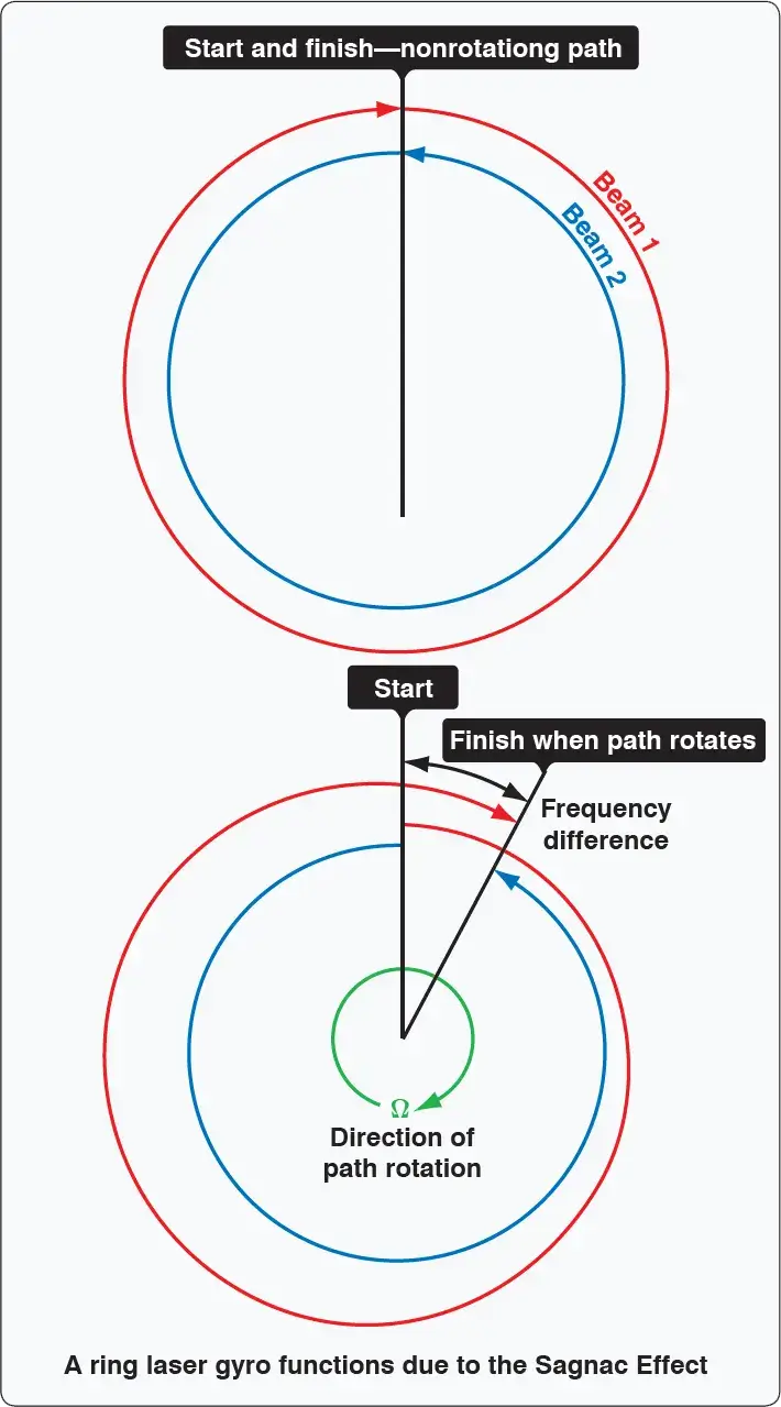 |
| Figure 4. Light traveling in opposite directions around a nonrotating path arrives at the end of the loop at the same time (top). When the path rotates, light traveling with the rotation must travel farther to complete one loop. Light traveling against the rotation completes the loop sooner (bottom) |
A laser is light amplification by stimulated emission of radiation. A laser operates by exciting atoms in plasma to release electromagnetic energy, or photons. A ring laser gyro produces laser beams that travel in opposite directions around a closed triangular cavity. The wavelength of the light traveling around the loop is fixed. As the loop rotates, the path the lasers must travel lengthens or shortens. The light wavelengths compress or expand to complete travel around the loop as the loop changes its effective length. As the wavelengths change, the frequencies also change.
By examining the difference in the frequencies of the two counterrotating beams of light, the rate at which the path is rotating can be measured. A piezoelectric dithering motor in the center of the unit vibrates to prevent lock-in of the output signal at low rotational speeds. It causes the unit to produce a slight humming sound during operation. [Figure 5]
 |
| Figure 5. The ring laser gyro is rugged, accurate, and free of friction |
An RLG is remotely mounted so the cavity path rotates around one of the axes of flight. The rate of frequency phase shift detected between the counterrotating lasers is proportional to the rate that the aircraft is moving about that axis. On aircraft, an RLG is installed for each axis of flight. Output can be used in analog instrumentation and autopilot systems. It is also easily made compatible for use by digital display computers and for digital autopilot computers.
RLGs are very rugged and have a long service life with virtually no maintenance due to their lack of moving parts. They measure movement about an axis extremely quickly and provide continuous output. They are extremely accurate and generally are considered superior to mechanical gyroscopes.
Microelectromechanical Based Attitude and Directional Systems
On aircraft, microelectromechanical systems (MEMS) devices save space and weight. Through the use of solid-state MEMS devices, reliability is increased primarily due to the lack of moving parts. The development of MEMS technology for use in aviation instrumentation integrates with the use of ADCs. This newest improvement in technology is low-cost and promises to proliferate through all forms of aviation.
MEMS for gyroscopic applications are used in small, general aviation aircraft, as well as larger commercial aircraft. Tiny vibration-based units with resistance and capacitance measuring pick-offs are accurate and reliable and only a few millimeters in length and width. They are normally integrated into a complete microelectronic solid-state chip designed to yield an output after various conditioning processes are performed. The chips, which are analogous to tiny circuit boards, can be packaged for installation inside a dedicated computer or module that is installed on the aircraft.
While a large mechanical gyroscope spins in a plane, its rigidity in space is used to observe and measure the movement of the aircraft. The basis of operation of many MEMS gyroscopes is the same despite their tiny size. The difference is that a vibrating or oscillating piezoelectric device replaces the spinning, weighted ring of the mechanical gyro. Still, once set in motion, any out-of-plane motion is detectable by varying microvoltages or capacitances detected through geometrically arranged pickups. Since piezoelectric substances have a relationship between movement and electricity, microelectrical stimulation can set a piezoelectric gyro in motion and the tiny voltages produced via the movement in the piezo can be extracted. They can be input as the required variables needed to compute attitude or direction information. [Figure 6]
 |
| Figure 6. The relative scale size of a MEMS gyro |
Other Attitude and Directional Systems
In modern aircraft, Attitude and Heading Reference Systems (AHRS) have taken the place of the gyroscope and other individual instruments. While MEMS devices provide part of the attitude information for the system, GPS, solid-state magnetometers, solid state accelerometers, and digital air data signals are all combined in an AHRS to compute and output highly reliable information for display on a cockpit panel. [Figure 7]
 |
| Figure 7. Instrumentation displayed within a glass cockpit using an attitude heading and reference system (AHRS) computer |
What are the two fundamental properties of a gyroscope?
What is the difference between a "Captive" and a "Free" gyro?
How does a Ring Laser Gyro (RLG) work without moving parts?
What is an Attitude and Heading Reference System (AHRS)?
RELATED POSTS