Most autopilot systems consist of four basic components, along with various switches and auxiliary units. The four basic components are: sensing elements, computing element, output elements, and command elements. Many advanced autopilot systems contain a fifth element: feedback or follow-up. This refers to signals sent as corrections are being made by the output elements to advise the autopilot of the progress being made. [Figure 1]
 |
| Figure 1. Typical analog autopilot system components |
Sensing Elements
The attitude and directional gyros, the turn coordinator, and an altitude control are the autopilot sensing elements. These units sense the movements of the aircraft. They generate electric signals that are used by the autopilot to automatically take the required corrective action needed to keep the aircraft flying as intended. The sensing gyros can be located in the cockpit mounted instruments. They can also be remotely mounted. Remote gyro sensors drive the servo displays in the cockpit panel, as well as provide the input signals to the autopilot computer.
Modern digital autopilots may use a variety of different sensors. MEMS gyros may be used or accompanied by the use of solid-state accelerometers and magnetometers. Rate-based systems may not use gyros at all. Various input sensors may be located within the same unit or in separate units that transfer information via digital data bus. Navigation information is also integrated via digital data bus connection to avionics computers.
Computer and Amplifier
The computing element of an autopilot may be analog or digital. Its function is to interpret the sensing element data, integrate commands and navigational input, and send signals to the output elements to move the flight controls as required to control the aircraft. An amplifier is used to strengthen the signal for processing, if needed, and for use by the output devices, such as servo motors. The amplifier and associated circuitry is the computer of an analog autopilot system. Information is handled in channels corresponding to the axis of control for which the signals are intended (i.e., pitch channel, roll channel, or yaw channel). Digital systems use solid state microprocessor computer technology and typically only amplify signals sent to the output elements.
Output Elements
The output elements of an autopilot system are the servos that cause actuation of the flight control surfaces. They are independent devices for each of the control channels that integrate into the regular flight control system. Autopilot servo designs vary widely depending on the method of actuation of the flight controls. Cable-actuated systems typically utilize electric servo motors or electro-pneumatic servos. Hydraulically actuated flight control systems use electro-hydraulic autopilot servos. Digital fly-by-wire aircraft utilize the same actuators for carrying out manual and autopilot maneuvers. When the autopilot is engaged, the actuators respond to commands from the autopilot rather than exclusively from the pilot. Regardless, autopilot servos must allow unimpeded control surface movement when the autopilot is not operating.
Aircraft with cable actuated control surfaces use two basic types of electric motor-operated servos. In one, a motor is connected to the servo output shaft through reduction gears. The motor starts, stops, and reverses direction in response to the commands of autopilot computer. The other type of electric servo uses a constantly running motor geared to the output shaft through two magnetic clutches. The clutches are arranged so that energizing one clutch transmits motor torque to turn the output shaft in one direction; energizing the other clutch turns the shaft in the opposite direction. [Figure 2] Electropneumatic servos can also be used to drive cable flight controls in some autopilot systems. They are controlled by electrical signals from the autopilot amplifier and actuated by an appropriate air pressure source. The source may be a vacuum system pump or turbine engine bleed air. Each servo consists of an electromagnetic valve assembly and an output linkage assembly.
 |
| Figure 2. A reversible motor with capstan and bridle cable (left), and a single-direction constant motor with clutches that drive the output shafts and control cable in opposite directions (right) single-direction constant motor with clutches that drive the output shafts and control cable in opposite directions |
Aircraft with hydraulically actuated flight control systems have autopilot servos that are electro-hydraulic. They are control valves that direct fluid pressure as needed to move the control surfaces via the control surface actuators. They are powered by signals from the autopilot computer. When the autopilot is not engaged, the servos allow hydraulic fluid to flow unrestricted in the flight control system for normal operation. The servo valves can incorporate feedback transducers to update the autopilot of progress during error correction.
Command Elements
The command unit, called a flight controller, is the human interface of the autopilot. It allows the pilot to tell the autopilot what to do. Flight controllers vary with the complexity of the autopilot system. By pressing the desired function buttons, the pilot causes the controller to send instruction signals to the autopilot computer, enabling it to activate the proper servos to carry out the command(s). Level flight, climbs, descents, turning to a heading, or flying a desired heading are some of the choices available on most autopilots. Many aircraft make use of a multitude of radio navigational aids. These can be selected to issue commands directly to the autopilot computer. [Figure 3]
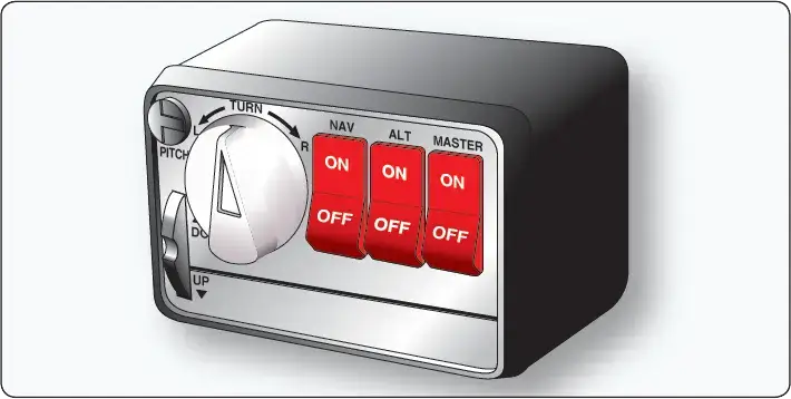 |
| Figure 3. An autopilot controller of a simple autopilot system |
In addition to an on/off switch on the autopilot controller, most autopilots have a disconnect switch located on the control wheel(s). This switch, operated by thumb pressure, can be used to disengage the autopilot system should a malfunction occur in the system or any time the pilot wishes to take manual control of the aircraft.
Feedback or Follow-up Element
As an autopilot maneuvers the flight controls to attain a desired flight attitude, it must reduce control surface correction as the desired attitude is nearly attained so the controls and aircraft come to rest on course. Without doing so, the system would continuously overcorrect. Surface deflection would occur until the desired attitude is attained. But movement would still occur as the surface(s) returned to pre-error position. The attitude sensor would once again detect an error and begin the correction process all over again.
Various electric feedback, or follow-up signals, are generated to progressively reduce the error message in the autopilot so that continuous overcorrection does not take place. This is typically done with transducers on the surface actuators or in the autopilot servo units. Feedback completes a loop as illustrated in Figure 4. This is called a closed-loop system.
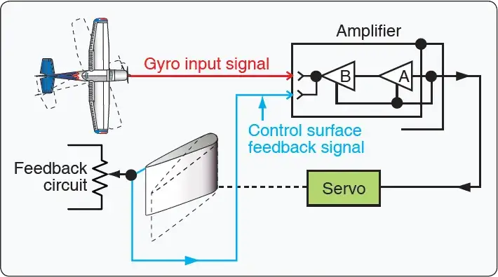 |
| Figure 4. Basic function of an analog autopilot system including follow-up or feedback signal |
A rate system receives error signals from a rate gyro that are of a certain polarity and magnitude that cause the control surfaces to be moved. As the control surfaces counteract the error and move to correct it, follow-up signals of opposite polarity and increasing magnitude counter the error signal until the aircraft’s correct attitude is restored. A displacement follow-up system uses control surface pickups to cancel the error message when the surface has been moved to the correct position.
Autopilot Functions
The following autopilot system description is presented to show the function of a simple analog autopilot. Most autopilots are far more sophisticated; however, many of the operating fundamentals are similar.
The automatic pilot system flies the aircraft by using electrical signals developed in gyro-sensing units. These units are connected to flight instruments that indicate direction, rate of turn, bank, or pitch. If the flight attitude or magnetic heading is changed, electrical signals are developed in the gyros. These signals are sent to the autopilot computer/amplifier and are used to control the operation of servo units.
A servo for each of the three control channels converts electrical signals into mechanical force, which moves the control surface in response to corrective signals or pilot commands. The rudder channel receives two signals that determine when and how much the rudder moves. The first signal is a course signal derived from a compass system. As long as the aircraft remains on the magnetic heading it was on when the autopilot was engaged, no signal develops. But, any deviation causes the compass system to send a signal to the rudder channel that is proportional to the angular displacement of the aircraft from the preset heading.
The second signal received by the rudder channel is the rate signal that provides information anytime the aircraft is turning about the vertical axis. This information is provided by the turn-and-bank indicator gyro. When the aircraft attempts to turn off course, the rate gyro develops a signal proportional to the rate of turn, and the course gyro develops a signal proportional to the amount of displacement. The two signals are sent to the rudder channel of the amplifier, where they are combined and their strength is increased. The amplified signal is then sent to the rudder servo. The servo turns the rudder in the proper direction to return the aircraft to the selected magnetic heading.
As the rudder surface moves, a follow-up signal is developed that opposes the input signal. When the two signals are equal in magnitude, the servo stops moving. As the aircraft arrives on course, the course signal reaches a zero value, and the rudder is returned to the streamline position by the follow-up signal.
The aileron channel receives its input signal from a transmitter located in the gyro horizon indicator. Any movement of the aircraft about its longitudinal axis causes the gyro-sensing unit to develop a signal to correct for the movement. This signal is amplified, phase-detected, and sent to the aileron servo, which moves the aileron control surfaces to correct for the error. As the aileron surfaces move, a follow-up signal builds up in opposition to the input signal. When the two signals are equal in magnitude, the servo stops moving. Since the ailerons are displaced from the streamline, the aircraft now starts moving back toward level flight with the input signal becoming smaller and the follow-up signal driving the control surfaces back toward the streamline position. When the aircraft has returned to level flight roll attitude, the input signal is again zero. At the same time, the control surfaces are streamlined, and the follow-up signal is zero.
The elevator channel circuits are similar to those of the aileron channel, with the exception that the elevator channel detects and corrects changes in pitch attitude of the aircraft. For altitude control, a remotely mounted unit containing an altitude pressure diaphragm is used. Similar to the attitude and directional gyros, the altitude unit generates error signals when the aircraft has moved from a preselected altitude. This is known as an altitude hold function. The signals control the pitch servos, which move to correct the error. An altitude select function causes the signals to continuously be sent to the pitch servos until a preselected altitude has been reached. The aircraft then maintains the preselected altitude using altitude hold signals.
Yaw Dampening
Many aircraft have a tendency to oscillate around their vertical axis while flying a fixed heading. Near continuous rudder input is needed to counteract this effect. A yaw damper is used to correct this motion. It can be part of an autopilot system or a completely independent unit. A yaw damper receives error signals from the turn coordinator rate gyro. Oscillating yaw motion is counteracted by rudder movement, which is made automatically by the rudder servo(s) in response to the polarity and magnitude of the error signal.
What are the four main components of an autopilot system?
- Sensing Elements: Gyros and sensors that detect aircraft movement.
- Computing Element: The "brain" that interprets data and decides on corrections.
- Output Elements: The servos that physically move the control surfaces.
- Command Elements: The flight controller where the pilot inputs instructions.
Why is the "Feedback" or "Follow-up" element important?
What is a Yaw Damper?
How does an autopilot servo interact with manual flight controls?
RELATED POSTS