Electronic flight instruments integrate multiple sources of flight and navigation data into a single display, improving situational awareness and reducing pilot workload.
Electronic Attitude Director Indicator (EADI)
EADI is an advanced version of traditional attitude indicators and electric attitude indicators. In addition to displaying the aircraft’s attitude, numerous other situational flight parameters are displayed. Most notable are those that relate to instrument approaches and the flight director command bars. Annunciation of active systems, such as the AFCS and navigation systems, is typical.
The concept behind EADI is to put all data related to the flight situation in close proximity for easy observation by the pilot. [Figure 1] Most EADIs can be switched between different display screens depending on the preference of the pilot and the phase of flight. EADIs vary from manufacturer to manufacturer and from one aircraft to another. However, most of the same information is displayed.
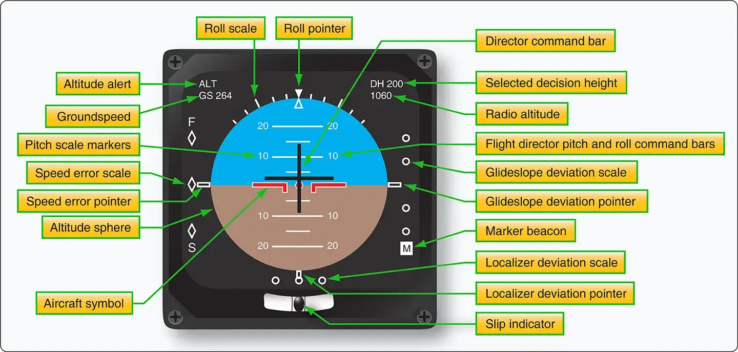 |
| Figure 1. Some of the many parameters and features of an electronic attitude director indicator (EADI) |
EADIs can be housed in a single instrument housing or can be part of an electronic display system. One such system, the electronic flight instrument system (EFIS), uses a cathode-ray tube (CRT) EADI display driven by a signal generator. Large-screen glass flight deck displays use LCD technology to display EADI information as part of an entire situational display directly in front of the pilot in the middle of the instrument panel. Regardless, the EADI is the primary flight instrument used for aircraft attitude information during instrument flying and especially during instrument approaches. It is almost always accompanied by an electronic horizontal situation indicator (EHSI) located just below it in the display panel.
Electronic Horizontal Situation Indicators (EHSI)
The EHSI is an evolved version of the horizontal situation indicator (HSI), which evolved from the gyroscopic direction indicator or directional gyro. The HSI incorporates directional information to two different navigational aids, as well as the heading of the aircraft. The EHSI does this and more. Its primary purpose is to display as much useful navigational information as possible.
In conjunction with a flight management computer and a display controller, an EHSI can display information in PLAN, MAP, VOR, and ILS modes. The PLAN mode shows a fixed map of the input flight plan. This usually includes all selected navigational aids for each flight segment and the destination airport. The MAP mode shows the aircraft against a detailed moving map background. Active and inactive navigational aids are shown, as well as other airports and waypoints. Weather radar information may be selected to be shown in scale as a background. Some HSIs can depict other air traffic when integrated with the Traffic Collision Avoidance System (TCAS). Unlike a standard HSI, an EHSI may show only the pertinent portion of the compass rose. Annunciation of active mode and selected features appear with other pertinent information, such as distance and arrival time to the next waypoint, airport designators, wind direction and speed, and more. [Figure 2] There are many different displays that vary by manufacturer.
 |
| Figure 2. An EHSI presents navigational information for the entire flight. The pilot selects the mode most useful for a particular phase of flight, ranging from navigational planning to instrument approach to landing. The MAP mode is used during most of the flight |
The VOR view of an EHSI presents a more traditional focus on a selected VOR, or other navigational station being used, during a particular flight segment. The entire compass rose, the traditional lateral deviation pointer, to/from information, heading, and distance information are standard. Other information may also be displayed. [Figure 3]
 |
| Figure 3. Approach and VOR mode presentation of an electronic horizontal situation indicator |
The ILS mode of an EHSI shows the aircraft in relation to the ILS approach aids and selected runway with varying degrees of detail. With this information displayed, the pilot need not consult printed airport approach information, allowing full attention to flying the aircraft.
What is an Electronic Attitude Director Indicator (EADI)?
How does an EHSI improve pilot navigation compared to a standard HSI?
What information is available in the EHSI "MAP" mode?
Why are EADI and EHSI displays usually paired together?
RELATED POSTS