A number of instruments inform the pilot of the aircraft’s condition and flight situations through the measurement of pressure. Pressure-sensing instruments can be found in the flight group and the engine group. They can be either direct reading or remote sensing. These are some of the most critical instruments on the aircraft and must accurately inform the pilot to maintain safe operations.
Pressure measurement involves some sort of mechanism that can sense changes in pressure. A technique for calibration and displaying the information is then added to inform the pilot. The type of pressure needed to be measured often makes one sensing mechanism more suited for use in a particular instance. The three fundamental pressure-sensing mechanisms used in aircraft instrument systems are the Bourdon tube, the diaphragm or bellows, and the solid-state sensing device.
A Bourdon tube is used to measure relatively high pressures and is illustrated in Figure 1. The open end of this coiled tube is fixed in place, and the other end is sealed and free to move.
 |
| Figure 1. The Bourdon tube is one of the basic mechanisms for sensing pressure |
When pressure is directed into the open end of the tube, the unfixed portion of the coiled tube tends to straighten out. The higher the pressure, the more the tube straightens. When the pressure is reduced, the tube recoils. A pointer is attached to this moving end of the tube, usually through a linkage of small shafts and gears. By calibrating this motion of the straightening tube, a face or dial of the instrument can be created. Thus, by observing the pointer movement along the scale of the instrument face positioned behind it, pressure increases and decreases are communicated to the pilot.
The Bourdon tube is the internal mechanism for many pressure gauges used on aircraft. Most Bourdon tubes are made from brass, bronze, or copper. Alloys of these metals can be made to coil and uncoil the tube consistently numerous times.
Bourdon tube gauges are simple and reliable. Some of the instruments that use a Bourdon tube mechanism include the engine oil pressure gauge, hydraulic pressure gauge, oxygen tank pressure gauge, and deice boot pressure gauge. Since the pressure of a heated liquid or gas increases as temperature increases, Bourdon tube mechanisms can also be used to measure temperature. This is done by calibrating the pointer connecting linkage and relabeling the face of the gauge with a temperature scale. Oil temperature gauges often employ Bourdon tube mechanisms. [Figure 2]
 |
| Figure 2. The Bourdon tube mechanism can be used to measure pressure or temperature by recalibrating the pointer’s connecting linkage and scaling instrument face to read in degrees Celsius or Fahrenheit |
Since the sensing and display of pressure or temperature information using a Bourdon tube mechanism usually occurs in a single instrument housing, they are most often direct reading gauges. But the Bourdon tube sensing device can also be used remotely. Regardless, it is necessary to direct the fluid to be measured into the Bourdon tube.
For example, a common direct-reading gauge measuring engine oil pressure and indicating it to the pilot in the flight deck is mounted in the instrument panel. A length of small tube connects a pressurized oil port on the engine, runs through the firewall, and into the back of the gauge. This setup is especially functional on light, single-engine aircraft in which the engine is mounted just forward of the instrument panel in the forward end of the fuselage.
However, a remote sensing unit can be more practical on twin-engine aircraft where the engines are a long distance from the flight deck pressure display. Here, the Bourdon tube’s motion is converted to an electrical signal and carried to the flight deck display via a wire. This is lighter and more efficient, eliminating the possibility of leaking fluids into the passenger compartment of the aircraft.
The diaphragm and bellows are two other basic sensing mechanisms employed in aircraft instruments for pressure measurement. They are most often used to measure relatively low pressures. The diaphragm is a hollow, thin-walled metal disc, usually corrugated. When pressure is introduced through an opening on one side of the disc, the entire disc expands. By placing linkage in contact against the other side of the disc, the movement of the pressurized diaphragm can be transferred to a pointer that registers the movement against the scale on the instrument face. [Figure 3]
 |
| Figure 3. A diaphragm used for measuring pressure. An evacuated sealed diaphragm is called an aneroid |
Diaphragms can also be sealed. The diaphragm can be evacuated before sealing, retaining absolutely nothing inside. When this is done, the diaphragm is called an aneroid. Aneroids are used in many flight instruments. A diaphragm can also be filled with a gas to standard atmospheric pressure and then sealed. Each of these diaphragms has its uses, which are described in the next section. The common factor in all is that the expansion and contraction of the side wall of the diaphragm is the movement that correlates to increasing and decreasing pressure.
When a number of diaphragm chambers are connected together, the device is called a bellows. This accordion-like assembly of diaphragms can be very useful when measuring the difference in pressure between two gases, called differential pressure. Just as with a single diaphragm, it is the movement of the side walls of the bellows assembly that correlates with changes in pressure and to which a pointer linkage and gearing is attached to inform the pilot. [Figure 4]
 |
| Figure 4. A bellows unit in a differential pressure gauge compares two different pressure values. End movement of the bellows away from the side with the highest pressure input occurs when the pressures in the bellows are not equal. The indicator linkage is calibrated to display the difference |
Diaphragms, aneroids, and bellows pressure sensing devices are often located inside the single instrument housing that contains the pointer and instrument dial read by the pilot on the instrument panel. Thus, many instruments that make use of these sensitive and reliable mechanisms are direct reading gauges. But, many remote sensing instrument systems also make use of the diaphragm and bellows.
In this case, the sensing device containing the pressure sensitive diaphragm or bellows is located remotely on the engine or airframe. It is part of a transducer that converts the pressure into an electrical signal. The transducer, or transmitter, sends the signal to the gauge in the flight deck, or to a computer, for processing and subsequent display of the sensed condition. Examples of instruments that use a diaphragm or bellows in a direct reading or remote sensing gauge are the altimeter, vertical speed indicator, cabin differential pressure gauge (in pressurized aircraft), and manifold pressure gauge.
Solid-state microtechnology pressure sensors are used in modern aircraft to determine the critical pressures needed for safe operation. Many of these have digital output ready for processing by electronic flight instrument computers and other onboard computers. Some sensors produce small electric signals that are converted to digital format for use by computers. As with the analog sensors described above, the key to the function of solid-state sensors is their consistent property changes as pressure changes.
The solid-state sensors used in most aviation applications exhibit varying electrical output or resistance changes when pressure changes occur. Crystalline piezoelectric, piezoresistor, and semiconductor chip sensors are most common. In the typical sensor, tiny wires are embedded in the crystal or pressure-sensitive semiconductor chip. When pressure deflects the crystal(s), a small amount of electricity is created or, in the case of a semiconductor chip and some crystals, the resistance changes. Since the current and resistance changes vary directly with the amount of deflection, outputs can be calibrated and used to display pressure values.
Nearly all of the pressure information needed for engine, airframe, and flight instruments can be captured and/or calculated through the use of solid-state pressure sensors in combination with temperature sensors. But continued use of aneroid devices for comparisons involving absolute pressure is notable. Solid-state pressure-sensing systems are remote sensing systems. The sensors are mounted on the aircraft at convenient and effective locations.
Types of Pressure
Pressure is a comparison between two forces. Absolute pressure exists when a force is compared to a total vacuum, or absolutely no pressure. It is necessary to define absolute pressure, because the air in the atmosphere is always exerting pressure on everything. Even when it seems there is no pressure being applied, like when a balloon is deflated, there is still atmospheric pressure inside and outside of the balloon. To measure that atmospheric pressure, it is necessary to compare it to a total absence of pressure, such as in a vacuum. Many aircraft instruments make use of absolute pressure values, such as the altimeter, the rate-of-climb indicator, and the manifold pressure gauge. As stated, this is usually done with an aneroid.
The most common type of pressure measurement is gauge pressure. This is the difference between the pressure to be measured and the atmospheric pressure. The gauge pressure inside the deflated balloon is therefore 0 pounds per square inch (psi) because the pressure inside the balloon is equal to the pressure outside the balloon. Gauge pressure is easily measured and is obtained by ignoring the fact that the atmosphere is always exerting its pressure on everything.
For example, a tire is filled with air to 32 psi at a sea level location and checked with a gauge to read 32 psi, which is the gauge pressure. The approximately 14.7 psi of air pressing on the outside of the tire is ignored. The absolute pressure in the tire is 32 psi plus the 14.7 psi that is needed to balance the 14.7 psi on the outside of the tire. So, the tire’s absolute pressure is approximately 46.7 psi. If the same tire is inflated to 32 psi at a location 10,000 feet above sea level, the air pressure on the outside of the tire would only be approximately 10 psi, due to the thinner atmosphere. The pressure inside the tire required to balance this would be 32 psi plus 10 psi, making the absolute pressure of the tire 42 psi. So, the same tire with the same amount of inflation and performance characteristics has different absolute pressure values. Gauge pressure, however, remains the same, indicating the tires are inflated identically. In this case, gauge pressure is more useful in informing us of the condition of the tire.
Gauge pressure measurements are simple and widely useful. They eliminate the need to measure varying atmospheric pressure to indicate or monitor a particular pressure situation. Gauge pressure should be assumed, unless otherwise indicated, or unless the pressure measurement is of a type known to require absolute pressure.
In many instances in aviation, it is desirable to compare the pressures of two different elements to arrive at useful information for operating the aircraft. When two pressures are compared in a gauge, the measurement is known as differential pressure and the gauge is a differential pressure gauge. An aircraft’s airspeed indicator is a differential pressure gauge. It compares ambient air pressure with ram air pressure to determine how fast the aircraft is moving through the air. A turbine’s engine pressure ratio (EPR) gauge is also a differential pressure gauge. It compares the pressure at the inlet of the engine with that at the outlet to indicate the thrust developed by the engine.
In aviation, there is also a commonly used pressure known as standard pressure. Standard pressure refers to an established or standard value that has been created for atmospheric pressure. This standard pressure value is 29.92 inches of mercury ("Hg), 1,013.2 hectopascals (hPa), or 14.7 psi. It is part of a standard day that has been established that includes a standard temperature of 15 °C at sea level.
Specific standard day values have also been established for air density, volume, and viscosity. All of these values are developed averages since the atmosphere is continuously fluctuating. They are used by engineers when designing instrument systems and are sometimes used by technicians and pilots. Often, using a standard value for atmospheric pressure is more desirable than using the actual value. For example, at 18,000 feet and above, all aircraft use 29.92 "Hg as a reference pressure for their instruments to indicate altitude. This results in altitude indications in all flight decks being identical. Therefore, an accurate means is established for maintaining vertical separation of aircraft flying at these high altitudes.
Pressure Instruments
Engine Oil Pressure
The most important instrument used by the pilot to perceive the health of an engine is the engine oil pressure gauge. [Figure 5] Oil pressure is usually indicated in psi. The normal operating range is typically represented by a green arc on the circular gauge. For exact acceptable operating range, consult the manufacturer’s operating and maintenance data.
 |
| Figure 5. An analog oil pressure gauge is driven by a Bourdon tube. Oil pressure is vital to engine health and must be monitored by the pilot |
In reciprocating and turbine engines, oil is used to lubricate and cool bearing surfaces where parts are rotating or sliding past each other at high speeds. A loss of pressurized oil to these areas would rapidly cause excessive friction and over temperature conditions, leading to catastrophic engine failure. As mentioned, aircraft using analog instruments often use direct reading Bourdon tube oil pressure gauges.
Figure 5 shows the instrument face of a typical oil pressure gauge of this type. Digital instrument systems use an analog or digital remote oil pressure sensing unit that sends output to the computer, driving the display of oil pressure value(s) on the aircraft’s cockpit display screens. Oil pressure may be displayed in a circular or linear gauge fashion and may even include a numerical value on screen. Often, oil pressure is grouped with other engine parameter displays on the same page or portion of a page on the display. Figure 6 shows this grouping on a Garmin G1000 digital instrument display system for general aviation aircraft.
 |
| Figure 6. Oil pressure indication with other engine-related parameters shown in a column on the left side of this digital cockpit display panel |
Manifold Pressure
In reciprocating engine aircraft, the manifold pressure gauge indicates the pressure of the air in the engine’s induction manifold. This is an indication of power being developed by the engine. The higher the pressure of the fuel-air mixture going into the engine, the more power it can produce. For normally aspirated engines, maximum manifold pressure would be slightly less than the ambient atmospheric pressure.
Turbocharged or supercharged engines pressurize the air being mixed with the fuel, so full power indications are above the ambient atmospheric pressure.
Most manifold pressure gauges are calibrated in inches of mercury, although digital displays may have the option to display in a different scale. A typical analog gauge makes use of an aneroid described above. When atmospheric pressure acts on the aneroid inside the gauge, the connected pointer indicates the current air pressure. A line running from the intake manifold into the gauge presents intake manifold air pressure to the aneroid, so the gauge indicates the absolute pressure in the intake manifold. An analog manifold pressure gauge, along with its internal workings, is shown in Figure 6.
The digital presentation of manifold pressure is at the top of the engine instruments displayed on the Garmin G1000 multifunctional display in Figure 7. The aircraft’s operating manual contains data on managing manifold pressure in relation to fuel flow and propeller pitch and for achieving various performance profiles during different phases of run-up and flight.
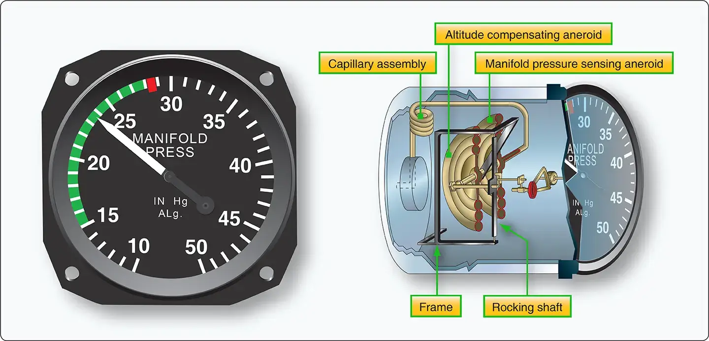 |
| Figure 7. An analog manifold pressure indicator instrument dial calibrated in inches of mercury (left). The internal workings of an analog manifold pressure gauge are shown on the right. Air from the intake manifold surrounds the aneroid causing it to deflect and indicate pressure on the dial through the use of linkage to the pointer (right) |
Engine Pressure Ratio (EPR)
Turbine engines have their own pressure indication that relates the power being developed by the engine. It is called the engine pressure ratio (EPR) indicator (EPR gauge). This gauge compares the total exhaust pressure to the pressure of the ram air at the inlet of the engine. With adjustments for temperature, altitude, and other factors, the EPR gauge presents an indication of the thrust being developed by the engine.
Since the EPR gauge compares two pressures, it is a differential pressure gauge. It is a remote-sensing instrument that receives its input from an engine pressure ratio transmitter or, in digital instrument systems displays, from a computer. The pressure ratio transmitter contains the bellows arrangement that compares the two pressures and converts the ratio into an electric signal used by the gauge for indication. [Figure 8]
 |
| Figure 8. Engine pressure ratio gauges |
Fuel Pressure
Fuel pressure gauges also provide critical information to the pilot. [Figure 9] Typically, fuel is pumped out of various fuel tanks on the aircraft for use by the engines. A malfunctioning fuel pump, or a tank that has been emptied beyond the point at which there is sufficient fuel entering the pump to maintain desired output pressure, is a condition that requires the pilot’s immediate attention.
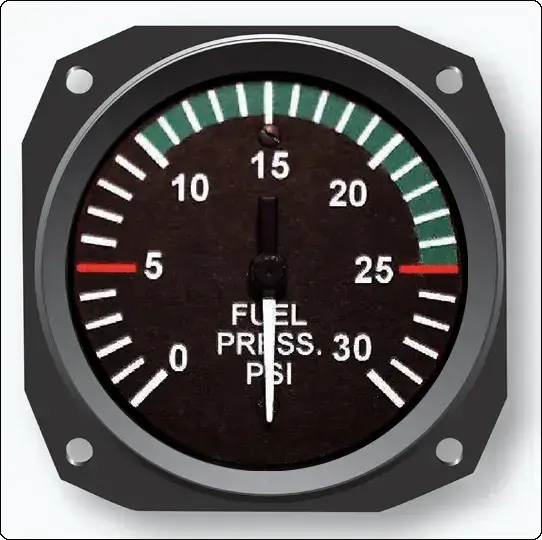 |
| Figure 9. A typical analog fuel pressure gauge |
While direct-sensing fuel pressure gauges using Bourdon tubes, diaphragms, and bellows sensing arrangements exist, it is particularly undesirable to run a fuel line into the cockpit, due to the potential for fire should a leak develop. Therefore, the preferred arrangement is to have whichever sensing mechanism that is used be part of a transmitter device that uses electricity to send a signal to the indicator in the cockpit. Sometimes, indications monitoring the fuel flow rate are used instead of fuel pressure gauges. Fuel flow indications are discussed in the fuel system section.
Hydraulic Pressure
Numerous other pressure monitoring gauges are used on complex aircraft to indicate the condition of various support systems not found on simple light aircraft. Hydraulic systems are commonly used to raise and lower landing gear, operate flight controls, apply brakes, and more. Sufficient pressure in the hydraulic system developed by the hydraulic pump(s) is required for normal operation of hydraulic devices.
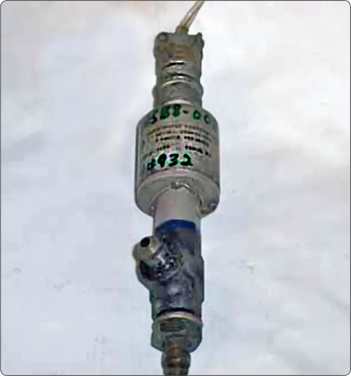
Hydraulic pressure gauges are often located in the flight deck and at or near the hydraulic system servicing point on the airframe. Remotely located indicators used by maintenance personnel are almost always direct reading Bourdon tube type gauges. Flight deck gauges usually have system pressure transmitted from sensors or computers electrically for indication. Figure 10 shows a hydraulic pressure transmitter in place in a high-pressure aircraft hydraulic system.
 |
| Figure 10. A hydraulic pressure transmitter senses and converts pressure into an electrical output for indication by the cockpit gauge or for use by a computer that analyzes and displays the pressure in the cockpit when requested or required |
Vacuum Pressure
Gyro pressure gauge, vacuum gauge, or suction gauge are all terms for the same gauge used to monitor the vacuum developed in the system that actuates the air driven gyroscopic flight instruments. Air is pulled through the instruments, causing the gyroscopes to spin. The speed at which the gyros spin needs to be within a certain range for correct operation. This speed is directly related to the suction pressure that is developed in the system. The suction gauge is extremely important in aircraft relying solely on vacuum-operated gyroscopic flight instruments.
Vacuum is a differential pressure indication, meaning the pressure to be measured is compared to atmospheric pressure through the use of a sealed diaphragm or capsule. The gauge is calibrated in inches of mercury. It shows how much less pressure exists in the system than in the atmosphere. Figure 11 shows a suction gauge calibrated in inches of mercury.
 |
| Figure 11. Vacuum suction gauge |
Pressure Switches
In aviation, it is often sufficient to simply monitor whether the pressure developed by a certain operating system is too high or too low, so that an action can take place should one of these conditions occur. This is often accomplished through the use of a pressure switch. A pressure switch is a simple device usually made to open or close an electric circuit when a certain pressure is reached in a system. It can be manufactured so that the electric circuit is normally open and can then close when a certain pressure is sensed, or the circuit can be closed and then opened when the activation pressure is reached. [Figure 12]
 |
| Figure 12. A pressure switch can be used in addition to, or instead of, a pressure gauge |
Pressure switches contain a diaphragm to which the pressure being sensed is applied on one side. The opposite side of the diaphragm is connected to a mechanical switching mechanism for an electric circuit. Small fluctuations or a buildup of pressure against the diaphragm move the diaphragm, but not enough to throw the switch. Only when pressure meets or exceeds a preset level designed into the structure of the switch does the diaphragm move far enough for the mechanical device on the opposite side to close the switch contacts and complete the circuit. [Figure 13] Each switch is rated to close (or open) at a certain pressure, and must only be installed in the proper location.
 |
| Figure 13. A normally open pressure switch positioned in an electrical circuit causes the circuit to be open as well. The switch closes, allowing electricity to flow when pressure is applied beyond the switch’s preset activation point. Normally, closed pressure switches allow electricity to flow through the switch in a circuit but open when pressure reaches a preset activation point, thus opening the electrical circuit |
A low oil pressure indication switch is a common example of how pressure switches are employed. It is installed in an engine so pressurized oil can be applied to the switch’s diaphragm. Upon starting the engine, oil pressure increases and the pressure against the diaphragm is sufficient to hold the contacts in the switch open. As such, current does not flow through the circuit and no indication of low oil pressure is given in the flight deck. Should a loss of oil pressure occur, the pressure against the diaphragm becomes insufficient to hold the switched contacts open. When the contacts close, they close the circuit to the low oil pressure indicator, usually a light, to warn the pilot of the situation.
Pressure gauges for various components or systems work similarly to those mentioned above. Some sort of sensing device, appropriate for the pressure being measured or monitored, is matched with an indicating display system. If appropriate, a properly rated pressure switch is installed in the system and wired into an indicating circuit.
Pitot-Static Systems
Some of the most important flight instruments derive their indications from measuring air pressure. Gathering and distributing various air pressures for flight instrumentation is the function of the pitot-static system.
Pitot Tubes and Static Vents
On simple aircraft, this may consist of a pitot-static system head or pitot tube with impact and static air pressure ports and leak-free tubing connecting these air pressure pickup points to the instruments that require the air for their indications. The altimeter, airspeed indicator, and vertical speed indicator are the three most common pitot-static instruments.
Figure 14 illustrates a simple pitot-static system connected to these three instruments. All three instruments are connected to the static pressure system. The airspeed indicator is additionally connected to the pitot pressure system. The altimeter is connected to the static pressure system.
 |
| Figure 14. A simple pitot-static system is connected to the primary flight instruments |
A pitot tube is open and faces into the airstream to receive the full force of the impact air pressure as the aircraft moves forward. This air passes through a baffled plate designed to protect the system from moisture and dirt entering the tube. Below the baffle, a drain hole is provided, allowing moisture to escape. The ram air is directed aft to a chamber in the shark fin of the assembly. An upright tube, or riser, leads this pressurized air out of the pitot assembly to the airspeed indicator.
The aft section of the pitot tube is equipped with small holes on the top and bottom surfaces that are designed to collect air pressure that is at atmospheric pressure in a static, or still, condition. The static section also contains a riser tube and the air is run out the pitot assembly through tubes and is connected to the altimeter, the airspeed indicator, and the vertical speed indicator. [Figure 15]
 |
| Figure 15. A typical pitot-static system head, or pitot tube, collects ram air and static pressure for use by the flight instruments |
Many pitot-static tube heads contain heating elements to prevent icing during flight. The pilot can send electric current to the element with a switch in the flight deck when ice-forming conditions exist. The pitot tube heat switch may be wired so that when the ignition switch is turned off when the aircraft is shut down, a pitot tube heater inadvertently left on does not continue to draw current and drain the battery. Caution should be exercised when near the pitot tube, as these heating elements make the tube too hot to be touched without receiving a burn.
The pitot-static tube is mounted on the outside of the aircraft at a point where the air is least likely to be turbulent. It is pointed in a forward direction parallel to the aircraft’s line of flight. The location may vary. Some are on the nose of the fuselage and others may be located on a wing. A few may even be found on the empennage. Various designs exist but the function remains the same, to capture impact air pressure and static air pressure and direct them to the proper instruments. [Figure 16]
 |
| Figure 16. Pitot-static system heads, or pitot tubes, can be of various designs and locations on airframes |
Most aircraft equipped with a pitot-static tube have an alternate source of static air pressure provided for emergency use. The pilot may select the alternate with a switch in the flight deck should it appear the flight instruments are not providing accurate indications. On low-flying unpressurized aircraft, the alternate static source may simply be air from the cabin. [Figure 17]
 |
| Figure 17. On unpressurized aircraft, an alternate source of static air is cabin air |
On pressurized aircraft, cabin air pressure may be significantly different than the outside ambient air pressure. If used as an alternate source for static air, instrument indications would be grossly inaccurate. In this case, multiple static vent pickup points are employed. All are located on the outside of the aircraft and plumbed so the pilot can select which source directs air into the instruments. On electronic flight displays, the choice is made for which source is used by the computer or by the flight crew.
Another type of pitot-static system provides for the location of the pitot and static sources at separate positions on the aircraft. The pitot tube in this arrangement is used only to gather ram air pressure. Separate static vents are used to collect static air pressure information. Usually, these are located flush on the side of the fuselage. [Figure 18]
 |
| Figure 18. Heated primary and alternate static vents located on the sides of the fuselage |
There may be two or more vents. A primary and alternate source vent is typical, as well as separate dedicated vents for the pilot and first officer’s instruments. Also, two primary vents may be located on opposite sides of the fuselage and connected with Y tubing for input to the instruments. This is done to compensate for any variations in static air pressure on the vents due to the aircraft’s attitude. Regardless of the number and location of separate static vents, they may be heated as well as the separate ram air pitot tube to prevent icing.
The pitot-static systems of complex, multiengine, and pressurized aircraft can be elaborate. Additional instruments, gauges, the autopilot system, and computers may need pitot and static air information. Figure 19 shows a pitot-static system for a pressurized multiengine aircraft with dual analog instrument panels in the flight deck.
 |
| Figure 19. Schematic of a typical pitot-static system on a pressurized multiengine aircraft |
The additional set of flight instruments for the copilot alters and complicates the pitot-static system plumbing. Additionally, the autopilot system requires static pressure information, as does the cabin pressurization unit. Separate heated sources for static air pressure are taken from both sides of the airframe to feed independent static air pressure manifolds; one each for the pilot’s flight instruments and the copilot’s flight instruments. This is designed to ensure that there is always one set of flight instruments operable in case of a malfunction.
Air Data Computers (ADC) and Digital Air Data Computers (DADC)
High performance and jet transport category aircraft pitot-static systems may be more complicated. These aircraft frequently operate at high altitude where the ambient temperature can exceed 50 °F below zero. The compressibility of air is also altered at high speeds and at high altitudes. Airflow around the fuselage changes, making it difficult to pick up consistent static pressure inputs. The pilot must compensate for all factors of air temperature and density to obtain accurate indications from instruments.
While many analog instruments have compensating devices built into them, the use of an air data computer (ADC) is common for these purposes on high-performance aircraft. Moreover, modern aircraft utilize digital air data computers (DADC). The conversion of sensed air pressures into digital values makes them more easily manipulated by the computer to output accurate information that has compensated for the many variables encountered. [Figure 20]
 |
| Figure 20. Teledyne’s 90004 TAS/Plus air data computer (ADC) computes air data information from the pitot-static pneumatic system, aircraft temperature probe, and barometric correction device to help create a clear indication of flight conditions |
Essentially, all pressures and temperatures captured by sensors are fed into theADC.Analog units utilize transducers to convert these to electrical values and manipulate them in various modules containing circuits designed to make the proper compensations for use by different instruments and systems. A DADC usually receives its data in digital format. Systems that do not have digital sensor outputs will first convert inputs into digital signals via an analog-to-digital converter.
Conversion can take place inside the computer or in a separate unit designed for this function. Then, all calculation and compensations are performed digitally by the computer. Outputs from the ADC are electric to drive servo motors or for use as inputs in pressurization systems, flight control units, and other systems. DADC outputs are distributed to these same systems and the flight deck display using a digital data bus.
There are numerous benefits of using ADCs. Simplification of pitot-static plumbing lines creates a lighter, simpler, system with fewer connections, so it is less prone to leaks and easier to maintain. One-time compensation calculations can be done inside the computer, eliminating the need to build compensating devices into numerous individual instruments or units of the systems using the air data.
DADCs can run a number of checks to verify the plausibility of data received from any source on the aircraft. Thus, the crew can be alerted automatically of a parameter that is out of the ordinary. Change to an alternate data source can also be automatic so accurate flight deck and systems operations are continuously maintained. In general, solid-state technology is more reliable and modern units are small and lightweight.
Figure 21 shows a schematic of how a DADC is connected into the aircraft’s pitot-static and other systems.
 |
| Figure 21. ADCs receive input from the pitot-static sensing devices and process them for use by numerous aircraft systems |
Pitot-Static Pressure-Sensing Flight Instruments
The basic flight instruments are directly connected to the pitot-static system on many aircraft. Analog flight instruments primarily use mechanical means to measure and indicate various flight parameters. Digital flight instrument systems use electricity and electronics to do the same. Discussion of the basic pitot-static flight instruments begins with analog instruments to which further information about modern digital instrumentation is added.
Altimeters and Altitude
An altimeter is an instrument that is used to indicate the height of the aircraft above a predetermined level, such as sea level or in the case of a radio/radar altimeter, the height of terrain beneath the aircraft. The most common way to measure this distance is rooted in discoveries made by scientists centuries ago. Seventeenth century work proving that the air in the atmosphere exerted pressure on the things around us led Evangelista Torricelli to the invention of the barometer.
Also in that century, using the concept of this first atmospheric air pressure measuring instrument, Blaise Pascal was able to show that a relationship exists between altitude and air pressure. As altitude increases, air pressure decreases. The amount that it decreases is measurable and consistent for any given altitude change. Therefore, by measuring air pressure, altitude can be determined. [Figure 22]
 |
| Figure 22. Air pressure is inversely related to altitude. This consistent relationship is used to calibrate the pressure altimeter |
Altimeters that measure the aircraft’s altitude by measuring the pressure of the atmospheric air are known as pressure altimeters. A pressure altimeter is made to measure the ambient air pressure at any given location and altitude. In aircraft, it is connected to the static vent(s) via tubing in the pitot-static system. The relationship between the measured pressure and the altitude is indicated on the instrument face, which is calibrated in feet. These devices are direct-reading instruments that measure absolute pressure.
An aneroid or aneroid bellows is at the core of the pressure altimeter’s inner workings. Attached to this sealed diaphragm are the linkages and gears that connect it to the indicating pointer. Static air pressure enters the airtight instrument case and surrounds the aneroid. At sea level, the altimeter indicates zero when this pressure is exerted by the ambient air on the aneroid. As air pressure is reduced by moving the altimeter higher in the atmosphere, the aneroid expands and displays altitude on the instrument by rotating the pointer. As the altimeter is lowered in the atmosphere, the air pressure around the aneroid increases and the pointer moves in the opposite direction. [Figure 23]
 |
| Figure 23. The internal arrangement of a sealed diaphragm pressure altimeter. At sea level and standard atmospheric conditions, the linkage attached to the expandable diaphragm produces an indication of zero. When altitude increases, static pressure on the outside of the diaphragm decreases and the aneroid expands, producing a positive indication of altitude. When altitude decreases, atmospheric pressure increases. The static air pressure on the outside of the diaphragm increases and the pointer moves in the opposite direction, indicating a decrease in altitude |
The face, or dial, of an analog altimeter is read similarly to a clock. As the longest pointer moves around the dial, it is registering the altitude in hundreds of feet. One complete revolution of this pointer indicates 1,000 feet of altitude.
The second-longest pointer moves more slowly. Each time it reaches a numeral, it indicates 1,000 feet of altitude. Once around the dial for this pointer is equal to 10,000 feet. When the longest pointer travels completely around the dial one time, the second-longest pointer moves only the distance between two numerals—indicating 1,000 feet of altitude has been attained. If so equipped, a third, shortest or thinnest pointer registers altitude in 10,000-foot increments. When this pointer reaches a numeral, 10,000 feet of altitude has been attained. Sometimes a black-and-white or red-and-white cross-hatched area is shown on the face on the instrument until the 10,000 foot level has been reached. [Figure 24]
 |
| Figure 24. A sensitive altimeter with three pointers and a crosshatched area displayed during operation below 10,000 feet |
Many altimeters also contain linkages that rotate a numerical counter in addition to moving pointers around the dial. This quick reference window allows the pilot to simply read the numerical altitude in feet. The motion of the rotating digits or drum-type counter during rapid climb or descent makes it difficult or impossible to read the numbers. Reference can then be directed to the classic clock-style indication.
Figure 25 illustrates the inner workings behind this type of mechanical digital display of pressure altitude.
 |
| Figure 25. A drum-type counter can be driven by the altimeter’s aneroid for numerical display of altitude. Drums can also be used for the altimeter’s setting indications |
True digital instrument displays can show altitude in numerous ways. Use of a numerical display rather than a reproduction of the clock-type dial is most common. Often a digital numeric display of altitude is given on the electronic primary flight display near the artificial horizon depiction. A linear vertical scale may also be presented to put this hard numerical value in perspective. An example of this type of display of altitude information is shown in Figure 26.
 |
| Figure 26. This primary flight display unit of a Garmin 1000 series glass cockpit instrumentation package for light aircraft indicates altitude using a vertical linear scale and a numerical counter. As the aircraft climbs or descends, the scale behind the black numerical altitude readout changes |
Accurate measurement of altitude is important for numerous reasons. The importance is magnified in instrument flight rules (IFR) conditions. For example, avoidance of tall obstacles and rising terrain relies on precise altitude indication, as does flying at a prescribed altitude assigned by air traffic control (ATC) to avoid colliding with other aircraft. Measuring altitude with a pressure measuring device is fraught with complications. Steps are taken to refine pressure altitude indication to compensate for factors that may cause an inaccurate display.
A major factor that affects pressure altitude measurements is the naturally occurring pressure variations throughout the atmosphere due to weather conditions. Different air masses develop and move over the earth’s surface, each with inherent pressure characteristics. These air masses cause the weather we experience, especially at the boundary areas between air masses known as fronts. Accordingly, at sea level, even if the temperature remains constant, air pressure rises and falls as weather system air masses come and go. The values in Figure 22, therefore, are averages for theoretical purposes.
To maintain altimeter accuracy despite varying atmospheric pressure, a means for setting the altimeter was devised. An adjustable pressure scale visible on the face of an analog altimeter known as a barometric or Kollsman window is set to read the existing atmospheric pressure that has been corrected to mean sea level (MSL). This tells the altimeter what barometric pressure is considered zero feet in altitude. The instrument will then indicate the altitude of the aircraft above mean sea level. This altitude, adjusted for atmospheric pressure changes due to weather and air mass pressure inconsistency, is known as the indicated altitude.
It must be noted that in flight below 18,000 feet, the altimeter setting is changed to match that of the closest available weather reporting station or airport. This keeps the altimeter accurate as the flight progresses.
While there was little need for exact altitude measurement in early fixed wing aviation, knowing one’s altitude provided the pilot with useful references while navigating in the three dimensions of the atmosphere. As air traffic grew and the desire to fly in any weather conditions increased, exact altitude measurement became more important and the altimeter was refined. In 1928, Paul Kollsman invented the means for adjusting an altimeter to reflect variations in air pressure from standard atmospheric pressure. The very next year, Jimmy Doolittle made his successful flight demonstrating the feasibility of instrument flight with no visual references outside of the flight deck using a Kollsman sensitive altimeter.
The term “pressure altitude” is used to describe the indication an altimeter gives when 29.92 is set in the Kollsman window. When flying in U.S. airspace above 18,000 feet mean sea level (MSL), pilots are required to set their altimeters to 29.92. With all aircraft referencing this standard pressure level, vertical separation between aircraft assigned to different altitudes by ATC should be assured. This is the case if all altimeters are functioning properly and pilots hold their assigned altitudes.
The actual, or true altitude, is less important than keeping aircraft from colliding, which is accomplished by all aircraft above 18,000 feet referencing the same barometric pressure (29.92 “Hg) on their altimeters. [Figure 27]
 |
| Figure 27. Above 18,000 feet MSL, all aircraft are required to set 29.92 as the reference pressure in the Kollsman window. The altimeter then reads pressure altitude. Depending on the atmospheric pressure that day, the true or actual altitude of the aircraft may be above or below what is indicated (pressure altitude) |
Temperature also affects the accuracy of an altimeter. The aneroid diaphragms used in altimeters are usually made of metal. Their elasticity changes as their temperature changes. This can lead to a false indication, especially at high altitudes when the ambient air is very cold. A bimetallic compensating device is built into many sensitive altimeters to correct for varying temperature. Figure 25 shows one such device on a drum-type altimeter.
Temperature also affects air density, which has great impact on the performance of an aircraft. Although this does not cause the altimeter to produce an errant reading, flight crews must be aware that performance changes with temperature variations in the atmosphere. The term density altitude describes altitude corrected for nonstandard temperature. That is, the density altitude is the standard day altitude (pressure altitude) at which an aircraft would experience similar performance as it would on the non-standard day currently being experienced.
For example, on a very cold day, the air is denser than on a standard day, so an aircraft performs as though it is at a lower altitude. The density altitude is lower on that day. On a very hot day, the reverse is true, and an aircraft performs as though it were at a higher elevation where the air is less dense. The density altitude is higher that day.
Conversion factors and charts have been produced so pilots can calculate the density altitude on any particular day. Inclusion of nonstandard air pressure due to weather systems and humidity can also be factored. So, while the effects of temperature on aircraft performance do not cause an altimeter to indicate falsely, an altimeter indication can be misleading in terms of aircraft performance if these effects are not considered. [Figure 28]
 |
| Figure 28. The effect of air temperature on aircraft performance is expressed as density altitude |
Other factors can cause an inaccurate altimeter indication. Scale error is a mechanical error whereby the scale of the instrument is not aligned so the altimeter pointers indicate correctly. Periodic testing and adjustment by trained technicians using calibrated equipment ensures scale error is kept to a minimum.
The pressure altimeter is connected to the pitot-static system and must receive an accurate sample of ambient air pressure to indicate the correct altitude. Position error, or installation error, is that inaccuracy caused by the location of the static vent that supplies the altimeter. While every effort is made to place static ports in undisturbed air, airflow over the airframe changes with the speed and attitude of the aircraft. The amount of this air pressure collection error is measured in test flights, and a correction table showing the variances can be included with the altimeter for the pilot’s use.
Normally, location of the static vents is adjusted during these test flights so that the position error is minimal. [Figure 29] Position error can be removed by the ADC in modern aircraft, so the pilot need not be concerned about this inaccuracy.
 |
| Figure 29. The location of the static vent is selected to keep altimeter position error to a minimum |
Static system leaks can affect the static air input to the altimeter or ADC resulting in inaccurate altimeter indications. It is for this reason that static system maintenance includes leak checks every 24 months, regardless of whether any discrepancy has been noticed. See the instrument maintenance section for further information on this mandatory check.
It should also be understood that analog mechanical altimeters are mechanical devices that often reside in a hostile environment. The significant vibration and temperature range swings encountered by the instruments and the pitot static system (i.e., the tubing connections and fittings) can sometimes create damage or a leak, leading to instrument malfunction. Proper care upon installation is the best preventive action. Periodic inspection and testing can also assure integrity.
The mechanical nature of the analog altimeter’s diaphragm pressure measuring apparatus has limitations. The diaphragm itself is only so elastic when responding to static air pressure changes. Hysteresis is the term for when the material from which the diaphragm is made takes a set during long periods of level flight. If followed by an abrupt altitude change, the indication lags or responds slowly while expanding or contracting during a rapid altitude change. While temporary, this limitation does cause an inaccurate altitude indication.
It should be noted that many modern altimeters are constructed to integrate into flight control systems, autopilots, and altitude monitoring systems, such as those used by ATC. The basic pressure-sensing operation of these altimeters is the same, but a means for transmitting the information is added.
Vertical Speed Indicator
An analog vertical speed indicator (VSI) may also be referred to as a vertical velocity indicator (VVI), or rate-of-climb indicator. It is a direct reading, differential pressure gauge that compares static pressure from the aircraft’s static system directed into a diaphragm with static pressure surrounding the diaphragm in the instrument case. Air is free to flow unrestricted in and out of the diaphragm but is made to flow in and out of the case through a calibrated orifice.
A pointer attached to the diaphragm indicates zero vertical speed when the pressure inside and outside the diaphragm are the same. The dial is usually graduated in 100s of feet per minute. A zeroing adjustment screw, or knob, on the face of the instrument is used to center the pointer exactly on zero while the aircraft is on the ground. [Figure 30]
 |
| Figure 30. A typical vertical speed indicator |
As the aircraft climbs, the unrestricted air pressure in the diaphragm lowers as the air becomes less dense. The case air pressure surrounding the diaphragm lowers more slowly, having to pass through the restriction created by the orifice. This causes unequal pressure inside and outside the diaphragm, which in turn causes the diaphragm to contract a bit and the pointer indicates a climb. The process works in reverse for an aircraft in a descent. If a steady climb or descent is maintained, a steady pressure differential is established between the diaphragm and case pressure surrounding it, resulting in an accurate indication of the rate of climb via graduations on the instrument face. [Figure 31]
 |
| Figure 31. The VSI is a differential pressure gauge that compares free-flowing static air pressure in the diaphragm with restricted static air pressure around the diaphragm in the instrument case |
A shortcoming of the rate-of-climb mechanism as described is that there is a lag of six to nine seconds before a stable differential pressure can be established that indicates the actual climb or descent rate of the aircraft. An instantaneous vertical speed indicator (IVSI) has a built-in mechanism to reduce this lag. A small, lightly sprung dashpot, or piston, reacts to the direction change of an abrupt climb or descent. As this small accelerometer does so, it pumps air into or out of the diaphragm, hastening the establishment of the pressure differential that causes the appropriate indication. [Figure 32]
 |
| Figure 32. The small dashpot in this IVSI reacts abruptly to a climb or descent pumping air into or out of the diaphragm causing an instantaneously vertical speed indication |
Gliders and lighter-than-air aircraft often make use of a variometer. This is a differential VSI that compares static pressure with a known pressure. It is very sensitive and gives an instantaneous indication. It uses a rotating vane with a pointer attached to it. The vane separates two chambers. One is connected to the aircraft’s static vent or is open to the atmosphere. The other is connected to a small reservoir inside the instrument that is filled to a known pressure.
As static air pressure increases, the pressure in the static air chamber increases and pushes against the vane. This rotates the vane and pointer, indicating a descent since the static pressure is now greater than the set amount in the chamber with reservoir pressure. During a climb, the reservoir pressure is greater than the static pressure; the vane is pushed in the opposite direction, causing the pointer to rotate and indicate a climb. [Figure 33]
 |
| Figure 33. A variometer uses differential pressure to indicate vertical speed. A rotating vane separating two chambers (one with static pressure, the other with a fixed pressure reservoir), moves the pointer as static pressure changes |
The rate-of-climb indication in a digitally displayed instrument system is computed from static air input to the ADC. An aneroid, or solid-state pressure sensor, continuously reacts to changes in static pressure. The digital clock within the computer replaces the calibrated orifice found on an analog instrument. As the static pressure changes, the computer’s clock can be used to develop a rate for the change. Using the known lapse rate conversion for air pressure as altitude increases or decreases, a figure for climb or descent in fpm can be calculated and sent to the flight deck. The vertical speed is often displayed near the altimeter information on the primary flight display. [Figure 26]
Airspeed Indicators
The airspeed indicator is another primary flight instrument that is also a differential pressure gauge. Ram air pressure from the aircraft’s pitot tube is directed into a diaphragm in an analog airspeed instrument case. Static air pressure from the aircraft static vent(s) is directed into the case surrounding the diaphragm. As the speed of the aircraft varies, the ram air pressure varies, expanding or contracting the diaphragm. Linkage attached to the diaphragm causes a pointer to move over the instrument face, which is calibrated in knots or miles per hour (mph). [Figure 34]
 |
| Figure 34. An airspeed indicator is a differential pressure gauge that compares ram air pressure with static pressure |
The relationship between the ram air pressure and static air pressure produces the indication known as indicated airspeed (IAS). As with the altimeter, there are other factors that must be considered in measuring airspeed throughout all phases of flight. These can cause inaccurate readings or indications that are not useful to the pilot in a particular situation. In analog airspeed indicators, the factors are often compensated for with ingenious mechanisms inside the case and on the instrument dial face. Digital flight instruments can have calculations performed in the ADC so the desired accurate indication is displayed.
While the relationship between ram air pressure and static air pressure is the basis for most airspeed indications, it can be more accurate. Calibrated airspeed (CAS) takes into account errors due to position error of the pitot static pickups. It also corrects for the nonlinear nature of the pitot static pressure differential when it is displayed on a linear scale. Analog airspeed indicators come with a correction chart that allows cross-referencing of indicated airspeed to calibrated airspeed for various flight conditions. These differences are typically very small and often are ignored. Digital instruments have these corrections performed in the ADC.
More importantly, indicated airspeed does not take into account temperature and air pressure differences needed to indicate true airspeed (TAS). These factors greatly affect airspeed indication. True airspeed, therefore, is the same as indicated airspeed when standard day conditions exist. But when atmospheric temperature or pressure varies, the relationship between the ram air pressure and static pressure alters. Analog airspeed instruments often include bimetallic temperature compensating devices that can alter the linkage movement between the diaphragm and the pointer movement.
There can also be an aneroid inside the airspeed indicator case that can compensate for non-standard pressures. Alternatively, true airspeed indicators exist that allow the pilot to set temperature and pressure variables manually with external knobs on the instrument dial. The knobs rotate the dial face and internal linkages to present an indication that compensates for non-standard temperature and pressure, resulting in a true airspeed indication. [Figure 35]
 |
| Figure 35. An analog true airspeed indicator. The pilot manually aligns the outside air temperature with the pressure altitude scale, resulting in an indication of true airspeed |
Digital flight instrument systems perform all of the calculations for true airspeed in the ADC. Ram air from the pitot tube and static air from the static vent(s) are run into the sensing portion of the computer. Temperature information is also input. This information can be manipulated and calculations performed so a true airspeed value can be digitally sent to the flight deck for display.
Refer to Figure 26 for the display of airspeed information on the primary flight display on a light aircraft. Note that similar to its position in the standard T configuration of an analog flight deck, the airspeed indication is just left of the artificial horizon display. Figure 36 showing T configuration.
 |
| Figure 36. The basic T arrangement of analog flight instruments |
Complications continue when considering airspeed indications and operating limitations. It is very important to keep high-speed aircraft from traveling faster than the speed of sound if they are not designed to do so. Even as an aircraft approaches the speed of sound, certain parts on the airframe may experience airflows that exceed it.
The problem with this is that near the speed of sound, shock waves can develop that can affect flight controls and, in some cases, can literally tear the aircraft apart if not designed for supersonic airflow. A further complication is that the speed of sound changes with altitude and temperature. So, a safe true airspeed at sea level could put the aircraft in danger at altitude due to the lower speed of sound. [Figure 37]
 |
| Figure 37. As temperatures fall at higher altitudes, the speed of sound is reduced |
In order to safeguard against these dangers, pilots monitor airspeed closely. A maximum allowable speed is established for the aircraft during certification flight testing. This speed is known as the critical Mach number or Mcrit. Mach is a ratio representing the speed of sound. The critical Mach number is expressed as a decimal of Mach such as 0.8 Mach. This means 8⁄10 of the speed of sound, regardless of what the actual speed of sound is at any particular altitude.
Many high performance aircraft are equipped with a Machmeter for monitoring Mcrit. The Machmeter is essentially an airspeed instrument that is calibrated in relation to Mach on the dial. Various scales exist for subsonic and supersonic aircraft. [Figure 38]
 |
| Figure 38. A Machmeter indicates aircraft speed relative to the speed of sound |
In addition to the ram air/ static air diaphragm arrangement, Machmeters also contain an altitude sensing diaphragm. It adjusts the input to the pointer so changes in the speed of sound due to altitude are incorporated into the indication. Some aircraft use a Mach/ airspeed indicator as shown in Figure 39.
 |
| Figure 39. A combination Mach/airspeed indicator shows airspeed with a white pointer and Mach number with a red and white striped pointer. Each pointer is driven by separate internal mechanisms |
This two-in-one instrument contains separate mechanisms to display the airspeed and Mach number. A standard white pointer is used to indicate airspeed in knots against one scale. A red and white striped pointer is driven independently to display the maximum allowable speed. Should the aircraft exceed this speed, it would result in an overspeed warning.
What are the three main types of pressure-sensing mechanisms?
- Bourdon Tube: Used for high pressures (e.g., oil and hydraulic systems).
- Diaphragm/Bellows: Used for low or differential pressures (e.g., airspeed and altimeters).
- Solid-State Sensors: Modern digital sensors using piezoelectric or semiconductor technology.
What is the difference between Absolute, Gauge, and Differential pressure?
How does a pitot-static system provide flight information?
Why is a Kollsman window necessary on an altimeter?
RELATED POSTS