Bleed Air Systems
Temperatures at high altitudes in which aircraft operate can be well below 0 °F. Combined with seasonally cold temperatures, this makes heating the cabin more than just a luxury. Pressurized aircraft that use air cycle air conditioning systems mix bleed air with cold air produced by the air cycle machine expansion turbine to obtain warm air for the cabin. This is discussed in the section that covers air cycle air conditioning in this site. Aircraft not equipped with air cycle air conditioning may be heated by one of a few possible methods.
Some turbine-powered aircraft not equipped with air cycle systems still make use of engine compressor bleed air to heat the cabin. Various arrangements exist. The bleed air is mixed with ambient air, or cabin return air, and distributed throughout the aircraft via ducting. The mixing of air can be done in a variety of ways. Mixing air valves, flow control valves, shutoff valves, and other various control valves are controlled by switches in the cockpit. One STC’d bleed air heat system uses mini-ejectors in helicopter cabins to combine bleed air with cabin air. All of these bleed air heating systems are simple and function well, as long as the valves, ducting, and controls are in operational condition.
Electric Heating Systems
Occasionally, an electric heating device is used to heat the aircraft. Electricity flowing through a heating element makes the element warm. A fan to blow air over the elements and into the cabin is used to transfer the heat. Other floor or sidewall elements simply radiate heat to warm the cabin. Electric heating element heaters require a significant amount of the aircraft’s generator output, which is better dedicated to the operation of other electrical devices. For this reason, they are not very common. However, their use on the ground when powered by a ground electrical power source preheats the cabin before passengers board and does not tax the electrical system.
Exhaust Shroud Heaters
Most single-engine light aircraft use exhaust shroud heating systems to heat the cabin. Ambient air is directed into a metal shroud, or jacket, that encases part of the engine’s exhaust system. The air is warmed by the exhaust and directed through a firewall heater valve into the cabin. This simple solution requires no electrical or engine power and it makes use of heat that would otherwise be wasted. [Figures 1 and 2]
 |
| Figure 1. The basic arrangement of an aircraft exhaust shroud heater |
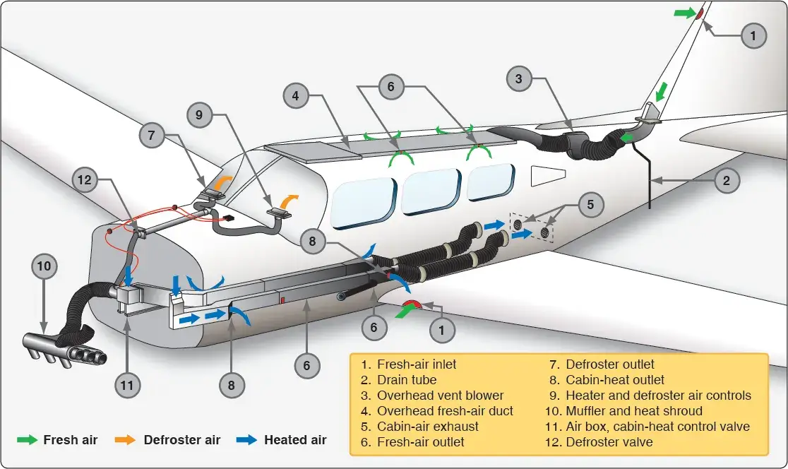 |
| Figure 2. The environmental system of a single-engine Piper aircraft with an exhaust shroud heating system |
A major concern of exhaust shroud heat systems is the possibility that exhaust gases could contaminate the cabin air. Even the slightest crack in an exhaust manifold could send enough carbon monoxide into the cabin to be fatal. Strict inspection procedures are in place to minimize this threat. Most involve pressurizing the exhaust system with air, while inspecting for leaks with a soapy solution. Some require the exhaust to be removed and pressurized while submerged under water to detect any leaks. Frequency of exhaust heat leak detection can be every 100 hours.
Occasionally, the exhaust system is slightly modified in a shroud heat configuration. For example, an exhaust muffler may have numerous welded studs attached, which increase heat transfer to the cabin air. Each weld point is a location for a potential leak. [Figure 3]
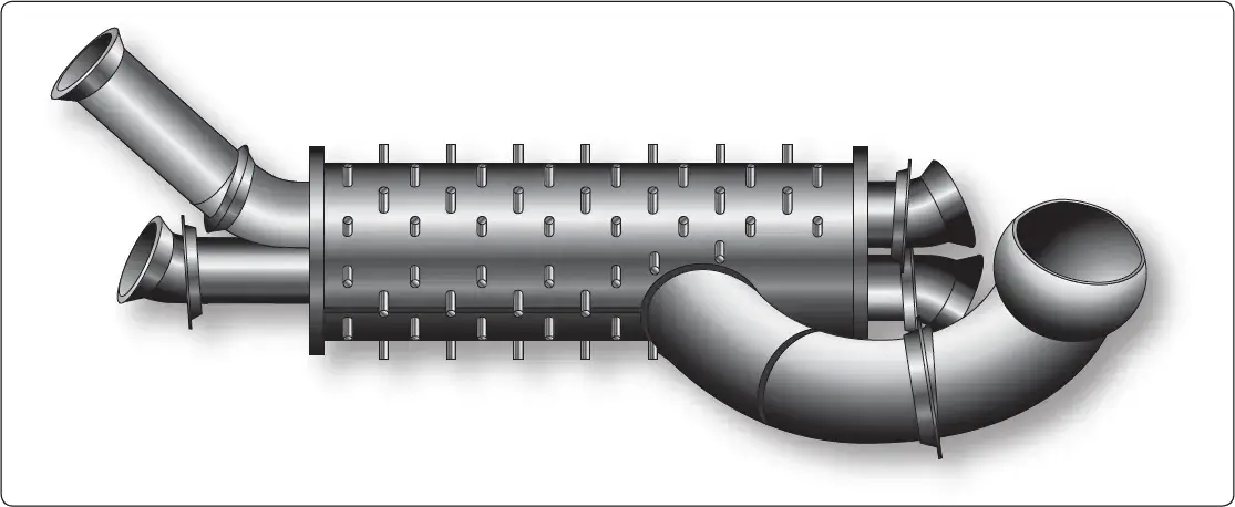 |
| Figure 3. An exhaust manifold with its shroud removed showing numerous welded studs used to increase heat transfer from the exhaust to the ambient air going to the cabin |
Regardless of age or condition, aircraft with exhaust shroud heating systems should contain a carbon monoxide detection device in the cockpit.
Combustion Heaters
An aircraft combustion heater is used on many small to medium sized aircraft. It is a heat source independent from the aircraft’s engine(s), although it does use fuel from the aircraft’s main fuel system. Combustion heaters are manufactured by a few different companies that supply the aviation industry. Most are similar to the description that follows. The most up to date units have electronic ignition and temperature control switches.
Combustion heaters are similar to exhaust shroud heaters in that ambient air is heated and sent to the cabin. The source of heat in this case is an independent combustion chamber located inside the cylindrical outer shroud of the heater unit. The correct amount of fuel and air are ignited in the air-tight inner chamber. The exhaust from combustion is funneled overboard. Ambient air is directed between the combustion chamber and the outer shroud. It absorbs the combustion heat by convection and is channeled into the cabin. [Figure 4] Refer to Figure 5 for the following descriptions of the combustion heater subsystems and heater operation.
 |
| Figure 4. A modern combustion heater |
 |
| Figure 5. A diagram of a typical combustion heater and its components |
Combustion Air System
The air used in the combustion process is ambient air scooped from outside the aircraft, or from the compartment in which the combustion heater is mounted. A blower ensures that the correct quantity and pressure of air are sent into the chamber.
Some units have regulators or a relief valve to ensure these parameters. The combustion air is completely separate from the air that is warmed and sent into the cabin.
Ventilating Air System
Ventilating air is the name of the air that is warmed and sent into the cabin. Typically, it comes into the combustion heater through a ram air intake. When the aircraft is on the ground, a ventilating air fan controlled by a landing gear squat switch operates to draw in the air. Once airborne, the fan ceases to operate as the ram air flow is sufficient. Ventilating air passes between the combustion chamber and the outer shroud of the combustion heater where it is warmed and sent to the cabin.
Fuel System
As mentioned, fuel for the combustion heater is drawn from an aircraft fuel tank. A constant pressure fuel pump with relief valve pulls the fuel through a filter. A main solenoid valve downstream delivers the fuel to the unit. The solenoid is controlled by the cabin heater switch in the cockpit and three safety switches located on the combustion heater. The first safety switch is a duct limit switch that keeps the valve closed should the unit not have enough ventilating airflow to keep it within the correct operating temperature range. The second is a pressure switch that must sense pressure from the combustion air fan to allow the solenoid to open. Fuel is delivered to the combustion chamber only if there is air there with which it can be mixed. Finally, an overheat switch also controls the main fuel supply solenoid. When an over temperature condition occurs, it closes the solenoid to stop the supply of fuel.
A secondary solenoid is located downstream of the main fuel supply solenoid. It is part of a fuel control unit that also houses a pressure regulator and an additional fuel filter. The valve opens and closes on command from the combustion heater thermostat. During normal operation, the heater cycles on and off by opening and closing this solenoid at the entrance to the combustion chamber. When opened, fuel flows through a nozzle that sprays it into the combustion chamber. [Figure 5]
Ignition System
Most combustion heaters have an ignition unit designed to receive aircraft voltage and step it up to fire a spark plug located in the combustion chamber. Older combustion heaters use vibrator-type ignition units. Modern units have electronic ignition. [Figure 6] The ignition is continuous when activated. This occurs when the heater switch is placed in the ON position in the cockpit, and the combustion air blower builds sufficient air pressure in the combustion chamber. Use of the proper spark plug for the combustion heater is essential. Check the manufacturer’s approved data. [Figure 7]
 |
| Figure 6. The fuel nozzle located at the end of the combustion chamber sprays aircraft fuel, which is lit by a continuous sparking ignition system spark plug |
 |
| Figure 7. Examples of ignition units used on combustion heaters |
Combustion Heater Controls
The combustion heater controls consist of a cabin heat switch and a thermostat. The cabin heat switch starts the fuel pump, opens the main fuel supply solenoid, and turns on the combustion air fan, as well as the ventilating air fan if the aircraft is on the ground. When the combustion air fan builds pressure, it allows the ignition unit to start. The thermostat sends power to open the fuel control solenoid when heat is needed. This triggers combustion in the unit and heat is delivered to the cabin. When the preselected temperature is reached, the thermostat cuts power to the fuel control solenoid and combustion stops. Ventilating air continues to circulate and carry heat away. When the temperature level falls to that below which the thermostat is set, the combustion heater cycles on again.
Safety Features
Various automatic combustion heater controls prevent operation of the heater when dangerous conditions exist. As stated, a duct limit switch cuts off fuel to the heater when there is not enough airflow to keep the heater duct below a preset temperature. This is usually caused by a lack of ventilating air flow. An overheat switch set at a higher temperature than the duct limit switch guards against overheat of any kind. It is designed to cut fuel to the combustion heater before an unwanted fire occurs. When this switch activates, a light is illuminated in the cockpit and the heater cannot be restarted until maintenance determines the cause. Some heaters contain a circuit to prevent fuel from being delivered to the combustion chamber if the ignition system is not working.
Maintenance and Inspection
Maintenance of combustion heaters consists of routine items, such as cleaning filters, checking spark plug wear, and ensuring inlets are not plugged. All maintenance and inspection of combustion heaters should be accomplished in accordance with the aircraft manufacturer’s instructions. Combustion heater manufacturers also produce maintenance guidelines that should be followed. Intervals between the performance of maintenance items and the time between overhauls must be followed to help ensure a properly functioning heater is available when it is needed.
Inspection of the combustion heater should be performed on schedule as provided by the manufacturer or whenever a malfunction is suspected. Inlets and outlets should be clear. All controls should be checked for freedom of operation and function. Close observation for any sign of fuel leaks or cracks in the combustion chamber and/or shroud should be made. All components should be secure. An operational check can also be made. Follow the manufacturer’s inspection criteria to ensure the combustion heater is in airworthy condition.