Aircraft air conditioning systems are designed to maintain a comfortable and safe cabin environment by controlling temperature, airflow, and humidity during flight and on the ground. Modern aircraft use either air cycle systems, which are common on turbine-powered aircraft, or vapor cycle systems, which are typically found on reciprocating-engine aircraft. Understanding how these systems cool and condition cabin air is important for aircraft maintenance technicians and pilots because they are closely integrated with the aircraft pneumatic, pressurization, and environmental control systems.
There are two types of air conditioning systems commonly used on aircraft. Air cycle air conditioning is used on most turbine-powered aircraft. It makes use of engine bleed air or APU pneumatic air during the conditioning process. Vapor cycle air conditioning systems are often used on reciprocating aircraft. This type system is similar to that found in homes and automobiles. Note that some turbine-powered aircraft also use vapor cycle air conditioning.
Air Cycle Air Conditioning
Air cycle air conditioning prepares engine bleed air to pressurize the aircraft cabin. The temperature and quantity of the air must be controlled to maintain a comfortable cabin environment at all altitudes and on the ground. The air cycle system is often called the air conditioning package or pack. It is usually located in the lower half of the fuselage or in the tail section of turbine-powered aircraft. [Figure 1]
 |
| Figure 1. Boeing 737 air cycle system. The photo is taken looking up into the air conditioning bay located in the lower fuselage on each side of the aircraft |
System Operation
Even with the frigid temperatures experienced at high altitudes, bleed air is too hot to be used in the cabin without being cooled. It is let into the air cycle system and routed through a heat exchanger where ram air cools the bleed air. This cooled bleed air is directed into an air cycle machine. There, it is compressed before flowing through a secondary heat exchange that cools the air again with ram air. The bleed air then flows back into the air cycle machine where it drives an expansion turbine and cools even further. Water is then removed and the air is mixed with bypassed bleed air for final temperature adjustment. It is sent to the cabin through the air distribution system.
By examining the operation of each component in the air cycle process, a better understanding can be developed of how bleed air is conditioned for cabin use. Refer to Figure 2, which diagrams the air cycle air conditioning system of the Boeing 737.
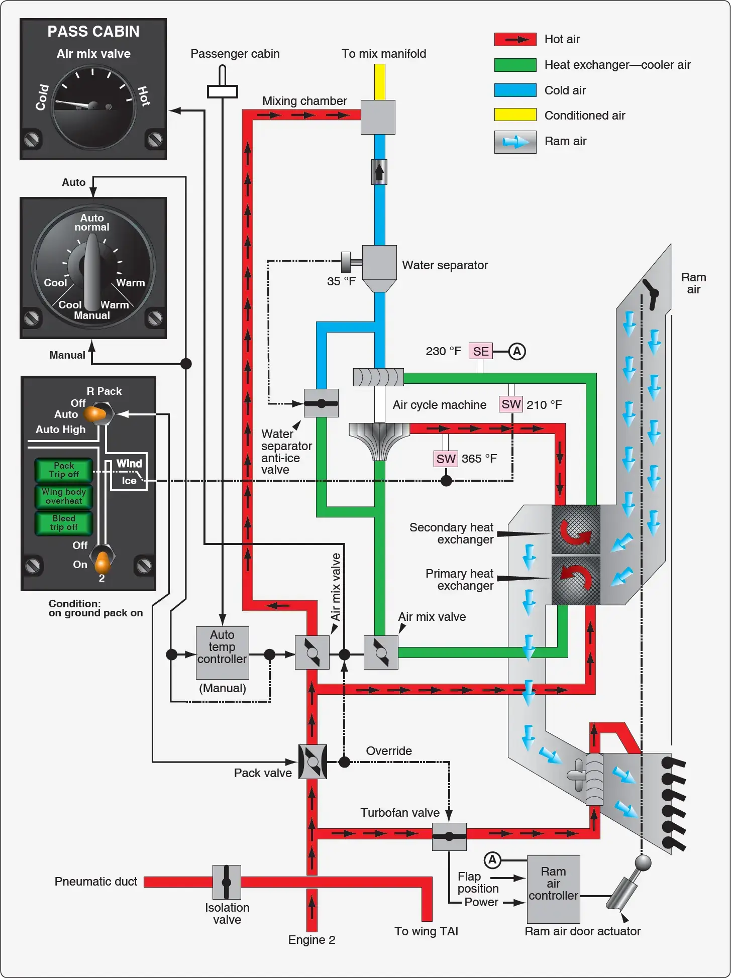 |
| Figure 2.The air cycle air conditioning system on a Boeing 737 |
Pneumatic System Supply
The air cycle air conditioning system is supplied with air by the aircraft pneumatic system. In turn, the pneumatic system is supplied by bleed air tap-offs on each engine compressor section or from the APU pneumatic supply. An external pneumatic air supply source may also be connected while the aircraft is stationary on the ground. In normal flight operations, a pneumatic manifold is supplied by the engine bleed air through the use of valves, regulators, and ducting. The air conditioning packs are supplied by this manifold as are other critical airframe systems, such as the anti-ice and hydraulic pressurization system.
Component Operation
Pack Valve
The pack valve is the valve that regulates bleed air from the pneumatic manifold into the air cycle air conditioning system. It is controlled with a switch from the air conditioning panel in the cockpit. Many pack valves are electrically controlled and pneumatically operated. Also known as the supply shutoff valve, the pack valve opens, closes, and modulates to allow the air cycle air conditioning system to be supplied with a designed volume of hot, pressurized air. [Figure 3] When an overheat or other abnormal condition requires that the air conditioning package be shut down, a signal is sent to the pack valve to close.
 |
| Figure 3. This pack valve drawing illustrates the complexity of the valve, which opens, closes, and modulates. It is manually actuated from the cockpit and automatically responds to supply and air cycle system parameter inputs |
Bleed Air Bypass
A means for bypassing some of the pneumatic air supplied to the air cycle air conditioning system around the system is present on all aircraft. This warm bypassed air must be mixed with the cold air produced by the air cycle system so the air delivered to the cabin is a comfortable temperature. It simultaneously controls the flow of bypassed air and air to be cooled to meet the requirements of the auto temperature controller. It can also be controlled manually with the cabin temperature selector in manual mode. Other air cycle systems may refer to the valve that controls the air bypassed around the air cycle cooling system as a temperature control valve, trim air pressure regulating valve, or something similar.
Primary Heat Exchanger
Generally, the warm air dedicated to pass through the air cycle system first passes through a primary heat exchanger. It acts similarly to the radiator in an automobile. A controlled flow of ram air is ducted over and through the exchanger, which reduces the temperature of the air inside the system. [Figure 4] A fan draws air through the ram air duct when the aircraft is on the ground so that the heat exchange is possible when the aircraft is stationary. In flight, ram air doors are modulated to increase or decrease ram air flow to the exchanger according to the position of the wing flaps. During slow flight, when the flaps are extended, the doors are open. At higher speeds, with the flaps retracted, the doors move toward the closed position reducing the amount of ram air to the exchanger. Similar operation is accomplished with a valve on smaller aircraft. [Figure 5]
 |
| Figure 4. The primary and secondary heat exchangers in an air cycle air conditioning system are of similar construction. They both cool bleed air when ram air passes over the exchanger coils and fins |
 |
| Figure 5. A ram air door controls the flow of air through the primary and secondary heat exchangers |
Refrigeration Turbine Unit or Air Cycle Machine and Secondary Heat Exchanger
The heart of the air cycle air conditioning system is the refrigeration turbine unit, also known as the air cycle machine (ACM). It is comprised of a compressor that is driven by a turbine on a common shaft. System air flows from the primary heat exchanger into the compressor side of the ACM. As the air is compressed, its temperature rises. It is then sent to a secondary heat exchanger, similar to the primary heat exchanger located in the ram air duct. The elevated temperature of the ACM compressed air facilitates an easy exchange of heat energy to the ram air.
The cooled system air, still under pressure from the continuous system air flow and the ACM compressor, exits the secondary heat exchanger. It is directed into the turbine side of the ACM. The steep blade pitch angle of the ACM turbine extracts more energy from the air as it passes through and drives the turbine. Once through, the air is allowed to expand at the ACM outlet, cooling even further. The combined energy loss from the air first driving the turbine and then expanding at the turbine outlet lowers the system air temperature to near freezing. [Figure 6]
 |
| Figure 6. A cutaway diagram of an air cycle machine. The main housing supports the single shaft to which the compressor and turbine are attached. Oil lubricates and cools the shaft bearings |
Water Separator
The cool air from the air cycle machine can no longer hold the quantity of water it could when it was warm. A water separator is used to remove the water from the saturated air before it is sent to the aircraft cabin. The separator operates with no moving parts. Foggy air from the ACM enters and is forced through a fiberglass sock that condenses and coalesces the mist into larger water drops. The convoluted interior structure of the separator swirls the air and water. The water collects on the sides of the separator and drains down and out of the unit, while the dry air passes through. A bypass valve is incorporated in case of a blockage. [Figure 7]
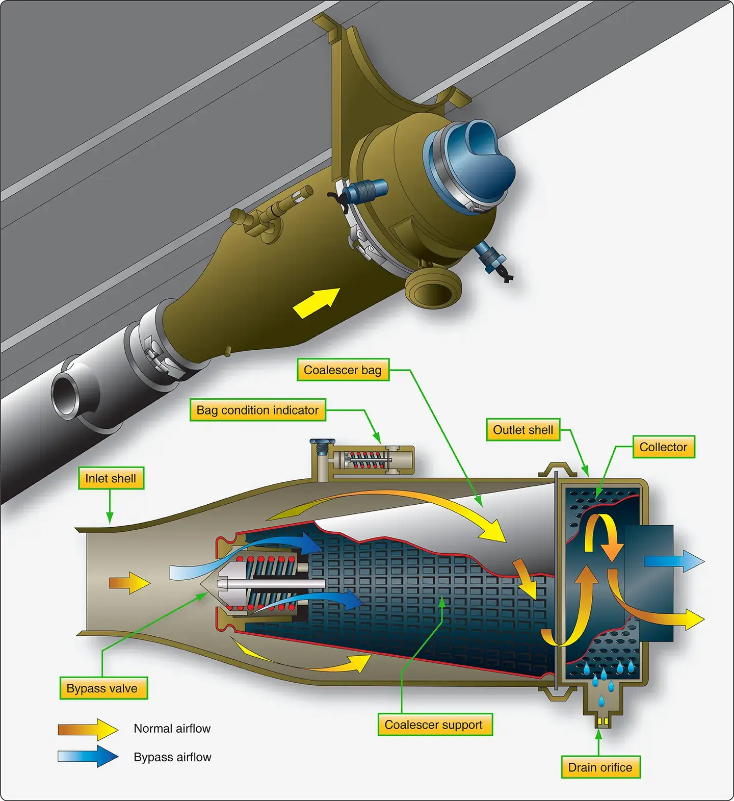 |
| Figure 7. A water separator coalesces and removes water by swirling the air/water mixture from ACM expansion turbine. Centrifugal force sends the water to the walls of the collector where it drains from the unit |
Refrigeration Bypass Valve
As mentioned, air exiting the ACM turbine expands and cools. It becomes so cold, it could freeze the water in the water separator, thus inhibiting or blocking airflow. A temperature sensor in the separator controls a refrigeration bypass valve designed to keep the air flowing through the water separator above freezing temperature. The valve is also identified by other names such as a temperature control valve, 35° valve, anti-ice valve, and similar. It bypasses warm air around the ACM when opened. The air is introduced into the expansion ducting, just upstream of the water separator, where it heats the air just enough to keep it from freezing. Thus, the refrigeration bypass valve regulates the temperature of the ACM discharge air so it does not freeze when passing through the water separator. This valve is visible in Figure 1 and is diagrammed in the system in Figure 2.
All air cycle air conditioning systems use at least one ram air heat exchanger and an air cycle machine with expansion turbine to remove heat energy from the bleed air, but variations exist. An example of a system different from that described above is found on the McDonnell Douglas DC-10. Bleed air from the pneumatic manifold is compressed by the air cycle machine compressor before it flows to a single heat exchanger. Condensed water from the water separator is sprayed into the ram air at its entrance to the exchanger to draw additional heat from the compressed bleed air as the water evaporates. A trim air valve for each cabin zone mixes bypassed bleed air with conditioned air in response to individual temperature selectors for each zone. When cooling air demands are low, a turbine bypass valve routes some heat exchanger air directly to the conditioned air manifold. [Figure 8]
 |
| Figure 8. The air cycle air conditioning system of a DC-10 transport category aircraft uses only one heat exchanger per ACM |
Cabin Temperature Control System
Typical System Operation
Most cabin temperature control systems operate in a similar manner. Temperature is monitored in the cabin, cockpit, conditioned air ducts, and distribution air ducts. These values are input into a temperature controller, or temperature control regulator, normally located in the electronics bay. A temperature selector in the cockpit can be adjusted to input the desired temperature. [Figure 9]
 |
| Figure 9. Typical temperature selectors on a transport category aircraft temperature control panel in the cockpit (left) and a business jet (right). On large aircraft, temperature selectors may be located on control panels located in a particular cabin air distribution zone |
The temperature controller compares the actual temperature signals received from the various sensors with the desired temperature input. Circuit logic for the selected mode processes these input signals. An output signal is sent to a valve in the air cycle air conditioning system. This valve has different names depending on the aircraft manufacturer and design of the environmental control systems (i.e., mixing valve, temperature control valve, trim air valve). It mixes warm bleed air that bypassed the air cycle cooling process with the cold air produced by it. By modulating the valve in response to the signal from the temperature controller, air of the selected temperature is sent to the cabin through the air distribution system.
Cabin temperature pickup units and duct temperature sensors used in the temperature control system are thermistors. Their resistance changes as temperature changes. The temperature selector is a rheostat that varies its resistance as the knob is turned. In the temperature controller, resistances are compared in a bridge circuit. The bridge output feeds a temperature regulating function. An electric signal output is prepared and sent to the valve that mixes hot and cold air. On large aircraft with separate temperature zones, trim air modulating valves for each zone are used. The valves modulate to provide the correct mix required to match the selected temperature. Cabin, flight deck, and duct temperature sensors are strategically located to provide useful information to control cabin temperature. [Figure 10]
 |
| Figure 10. The temperature control system of a Boeing 777 combines the use of zone and duct temperature sensors with trim air modulating valves for each zone. Redundant digital left and right cabin temperature controllers process temperature input signals from the sensors and temperature selectors on the cockpit panel and throughout the aircraft to modulate the valves |
Vapor Cycle Air Conditioning
The absence of a bleed air source on reciprocating engine aircraft makes the use of an air cycle system impractical for conditioning cabin air. Vapor cycle air conditioning is used on most non-turbine aircraft that are equipped with air conditioning. However, it is not a source of pressurizing air, as conditioned air from the air cycle system is on turbine-powered aircraft. The vapor cycle system only cools the cabin. If an aircraft equipped with a vapor cycle air conditioning system is pressurized, it uses one of the sources discussed in the pressurization section above. Vapor cycle air conditioning is a closed system used solely for the transfer of heat from inside the cabin to outside of the cabin. It can operate on the ground and in flight.
Theory of Refrigeration
Energy can be neither created nor destroyed; however, it can be transformed and moved. This is what occurs during vapor cycle air conditioning. Heat energy is moved from the cabin air into a liquid refrigerant. Due to the additional energy, the liquid changes into a vapor. The vapor is compressed and becomes very hot. It is removed from the cabin where the very hot vapor refrigerant transfers its heat energy to the outside air. In doing so, the refrigerant cools and condenses back into a liquid. The refrigerant returns to the cabin to repeat the cycle of energy transfer. [Figure 11]
 |
| Figure 11. In vapor cycle air conditioning, heat is carried from the cabin to the outside air by a refrigerant which changes from a liquid to a vapor and back again |
Heat is an expression of energy, typically measured by temperature. The higher the temperature of a substance, the more energy it contains. Heat always flows from hot to cold. These terms express the relative amount of energy present in two substances. They do not measure the absolute amount of heat present. Without a difference in energy levels, there is no transfer of energy (heat).
Adding heat to a substance does not always raise its temperature. When a substance changes state, such as when a liquid changes into a vapor, heat energy is absorbed. This is called latent heat. When a vapor condenses into a liquid, this heat energy is given off. The temperature of a substance remains constant during its change of state. All energy absorbed or given off, the latent heat, is used for the change process. Once the change of state is complete, heat added to a substance raises the temperature of the substance. After a substance changes state into a vapor, the rise in temperature of the vapor caused by the addition of still more heat is called superheat.
The temperature at which a substance changes from a liquid into a vapor when heat is added is known as its boiling point. This is the same temperature at which a vapor condenses into a liquid when heat is removed. The boiling point of any substance varies directly with pressure. When pressure on a liquid is increased, its boiling point increases, and when pressure on a liquid is decreased, its boiling point also decreases. For example, water boils at 212 °F at normal atmospheric temperature (14.7 psi). When pressure on liquid water is increased to 20 psi, it does not boil at 212 °F. More energy is required to overcome the increase in pressure. It boils at approximately 226.4 °F. The converse is also true. Water can also boil at a much lower temperature simply by reducing the pressure upon it. With only 10 psi of pressure upon liquid water, it boils at 194 °F. [Figure 12]
 |
| Figure 12. Boiling point of water changes as pressure changes |
Vapor pressure is the pressure of the vapor that exists above a liquid that is in an enclosed container at any given temperature. The vapor pressure developed by various substances is unique to each substance. A substance that is said to be volatile, develops high vapor pressure at standard day temperature (59 °F). This is because the boiling point of the substance is much lower. The boiling point of tetrafluoroethane (R134a), the refrigerant used in most aircraft vapor cycle air conditioning systems, is approximately –15 °F. Its vapor pressure at 59 °F is about 71 psi. The vapor pressure of any substance varies directly with temperature.
Basic Vapor Cycle
Vapor cycle air conditioning is a closed system in which a refrigerant is circulated through tubing and a variety of components. The purpose is to remove heat from the aircraft cabin. While circulating, the refrigerant changes state. By manipulating the latent heat required to do so, hot air is replaced with cool air in the aircraft cabin.
To begin, R134a is filtered and stored under pressure in a reservoir known as a receiver dryer. The refrigerant is in liquid form. It flows from the receiver dryer through tubing to an expansion valve. Inside the valve, a restriction in the form of a small orifice blocks most of the refrigerant. Since it is under pressure, some of the refrigerant is forced through the orifice. It emerges as a spray of tiny droplets in the tubing downstream of the valve. The tubing is coiled into a radiator type assembly known as an evaporator. A fan is positioned to blow cabin air over the surface of the evaporator. As it does, the heat in the cabin air is absorbed by the refrigerant, which uses it to change state from a liquid to a vapor. So much heat is absorbed that the cabin air blown by the fan across the evaporator cools significantly. This is the vapor cycle conditioned air that lowers the temperature in the cabin.
The gaseous refrigerant exiting the evaporator is drawn into a compressor. There, the pressure and the temperature of the refrigerant are increased. The high-pressure high-temperature gaseous refrigerant flows through tubing to a condenser. The condenser is like a radiator comprised of a great length of tubing with fins attached to promote heat transfer. Outside air is directed over the condenser. The temperature of the refrigerant inside is higher than the ambient air temperature, so heat is transferred from the refrigerant to the outside air. The amount of heat given off is enough to cool the refrigerant and to condense it back to a high-pressure liquid. It flows through tubing and back into the receiver dryer, completing the vapor cycle.
There are two sides to the vapor cycle air conditioning system. One accepts heat and is known as the low side. The other gives up heat and is known as the high side. The low and high refer to the temperature and pressure of the refrigerant. As such, the compressor and the expansion valve are the two components that separate the low side from the high side of the cycle. [Figure 13] Refrigerant on the low side is characterized as having low pressure and temperature. Refrigerant on the high side has high pressure and temperature.
 |
| Figure 13. A basic vapor cycle air conditioning system. The compressor and the expansion valve are the two components that separate the low side from the high side of the cycle. This figure illustrates this division. Refrigerant on the low side is characterized as having low pressure and temperature. Refrigerant on the high side has high pressure and temperature |
Vapor Cycle Air Conditioning System Components
By examining each component in the vapor cycle air conditioning system, greater insight into its function can be gained. The Vapor Cycle Air Conditioning System Components post discusses the following components in greater detail:
- Refrigerant
- Receiver Dryer
- Expansion Valve
- Evaporator
- Compressor
- Condenser and Service Valves
Vapor Cycle Air Conditioning Servicing Equipment
Special servicing equipment is used to service vapor cycle air conditioning systems. The U.S. Environmental Protection Agency (EPA) has declared it illegal to release R12 refrigerant into the atmosphere. Equipment has been designed to capture the refrigerant during the servicing process. Although R134a does not have this restriction, it is illegal in some locations to release it to the atmosphere, and it may become universally so in the near future. It is good practice to capture all refrigerants for future use, rather than to waste them or to harm the environment by releasing them into the atmosphere. Capturing the refrigerant is a simple process designed into the proper servicing equipment. The technician should always be vigilant to use the approved refrigerant for the system being serviced and should follow all manufacturer instructions.
The Vapor Cycle Air Conditioning Servicing Equipment post discusses the following equipment in greater detail:
- Manifold Set Gauges Hoses, and Fittings
- Full Service Refrigerant Recovery, Recycling, Evacuation, and Recharging Units
- Refrigerant Source
- Vacuum Pumps
- Leak Detectors
RELATED POSTS