Vapor cycle air conditioning systems can give many hours of reliable, maintenance-free service. Periodic visual inspections, tests, and refrigerant level and oil level checks may be all that is required for some time. Follow the manufacturer’s instructions for inspection criteria and intervals.
Visual Inspection
All components of any vapor cycle system should be checked to ensure they are secure. Be vigilant for any damage, misalignment, or visual signs of leakage. The evaporator and condenser fins should be checked to ensure they are clean, unobstructed, and not folded over from an impact. Dirt and inhibited airflow through the fins can prevent effective heat exchange to and from the refrigerant. Occasionally, these units can be washed. Since the condenser often has ram air ducted to it or extends into the airstream, check for the presence of debris that may restrict airflow. Hinged units should be checked for security and wear. The mechanism to extend and retract the unit should function as specified, including the throttle position switch present on many systems. It is designed to cut power to the compressor clutch and retract the condenser at full power settings. Condensers may also have a fan to pull air over them during ground operation. It should be checked to ensure it functions correctly. [Figure 1]
 |
| Figure 1. Damaged fins on a condenser |
Be sure the capillary temperature feedback sensor to the expansion valve is securely attached to the evaporator outlet. Also, check the security of the pressure sensor and thermostat sensor if the system has them. The evaporator should not have ice on the outside. This prevents proper heat exchange to the refrigerant from the warm cabin air blown over the unit.
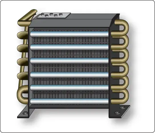
The fan blower should be checked to ensure it rotates freely. Depending on the system, it should run whenever the cooling switch is selected and should change speeds as the selector is rotated to more or less cooling. Sometimes systems low on refrigerant can cause ice on the evaporator, as can a faulty expansion valve or feedback control line. Ice formation anywhere on the outside of a vapor cycle air conditioning system should be investigated for cause and corrected. [Figure 2]
 |
| Figure 2. Ice on the evaporator coils is cause for investigation. It prevents proper heat exchange to the refrigerant |
Security and alignment of the compressor is critical and should be checked during inspection. Belt-driven compressors need to have proper belt tension to function properly. Check the manufacturer’s data for information on how to determine the condition and tension of the belt, as well as how to make adjustments. Oil level should be sufficient. Typically, 1⁄4 ounce of oil is added for each pound of refrigerant added to the system. When changing a component, additional oil may need to be added to replace that which is trapped in the replaced unit. Always use the oil specified in the manufacturer’s maintenance manual.
Leak Test
As mentioned under the leak detector section above, leaks in a vapor cycle air conditioning system must be discovered and repaired. The most obvious sign of a possible leak is a low refrigerant level. Bubbles present in the sight glass of the receiver dryer while the system is operating indicate more refrigerant is needed. A system check for a leak may be in order. Note that vapor cycle systems normally lose a small amount of refrigerant each year. No action is needed if this amount is within limits.
Occasionally, all of the refrigerant escapes from the system. No bubbles are visible in the sight glass, but the complete lack of cooling indicates the refrigerant has leaked out. To locate the leak point, the system needs to be partially charged with refrigerant so leak detection methods can be employed. About 50 psi of refrigerant in the high and low sides should be sufficient for a leak check. By introducing the refrigerant into the high side, pressure indicated on the low side gauge verifies the orifice in the expansion valve is not clogged. When all refrigerant is lost due to a leak, the entire system should be checked. Each fitting and connection should be inspected visually and with a leak detector.
When a vapor cycle air conditioning system loses all of its refrigerant charge, air may enter the system. Water may also enter since it is in the air. This means that a full system evacuation must be performed after the leak is found and repaired. By establishing only a 50 psi charge in a depleted system, the leak(s) become detectable, but time and refrigerant are not wasted prior to evacuation. System evacuation is discussed below.
Performance Test
Verification of proper operation of a vapor cycle air conditioning system is often part of a performance test. This involves operating the system and checking parameters to ensure they are in the normal range. A key indication of system performance is the temperature of the air that is cooled by the evaporator. This can be measured at the air outflow from the evaporator or at a nearby delivery duct outlet. An ordinary thermometer should read 40–50 °F, with the controls set to full cold after the system has been allowed to operate for a few minutes. Manufacturer’s instructions include information on where to place the thermometer and the temperature range that indicates acceptable performance.
Pressures can also be observed to indicate system performance. Typically, low side pressure in a vapor cycle system operating normally is 10–50 psi, depending on ambient temperature. High side pressure is between 125 and 250 psi, again, depending on ambient temperature and the design of the system. All system performance tests are performed at a specified engine rpm (stable compressor speed) and involve a period of time to stabilize the operation of the vapor cycle. Consult the manufacturer’s instructions for guidance.
Feel Test
A quick reference field test can be performed on a vapor cycle air conditioning system to gauge its health. In particular, components and lines in the high side (from the compressor to the expansion valve) should be warm or hot to the touch. The lines on both sides of the receiver dryer should be the same temperature. Low side lines and the evaporator should be cool. Ice should not be visible on the outside of the system. If any discrepancies exist, further investigation is needed. On hot, humid days, the cooling output of the vapor cycle system may be slightly compromised due to the volume of water condensing on the evaporator.
Purging the System
Purging the system means emptying it of its refrigerant charge. Since the refrigerant must be captured, a service cart with this capability should be used. By connecting the hoses to the high side and low side service valves and selecting recover, cart solenoid valves position so that a system purging compressor pumps the refrigerant out of the vapor cycle system and into a recovery tank.
Vapor cycle systems must be properly purged before opening for maintenance or component replacement. Once opened, precautions should be taken to prevent contaminants from entering the system. When suspicion exists that the system has been contaminated, such as when a component has catastrophically failed, it can be flushed clean. A special flushing fluid formulated for vapor cycle air conditioning systems should be used. The receiver dryer is removed from the system for flushing and a new unit is installed, as it contains fresh filters. Follow the aircraft manufacturer’s instructions.
Checking Compressor Oil
The compressor is a sealed unit in the vapor cycle system that is lubricated with oil. Any time the system is purged, it is an opportunity to check the oil quantity in the compressor crankcase. This is often done by removing a filler plug and using a dipstick. Oil quantity should be maintained within the proper range using oil recommended by the manufacturer. Be certain to replace the filler plug after checking or adding oil. [Figure 3]
 |
| Figure 3. Checking the compressor oil when the system is open |
Evacuating the System
Only a few drops of moisture can contaminate a vapor cycle air conditioning system. If this moisture freezes in the expansion valve, it could completely block the refrigerant flow. Water is removed from the system by evacuation. Anytime the system refrigerant charge falls below atmospheric pressure, the refrigerant is lost, or the system is opened, it must be evacuated before recharging.
Evacuating a vapor cycle air conditioning system is also known as pumping down the system. A vacuum pump is connected and pressure inside the system is reduced to vaporize any water that may exist. Continued operation of the vacuum pump draws the water vapor from the system. A typical pump used for evacuating an air conditioning system can reduce system pressure to about 29.62 "Hg (gauge pressure). At this pressure, water boils at 45 °F. Operate the vacuum pump to achieve the recommended gauge pressure. Hold this vacuum for as long as the manufacturer specifies.
As long as a vapor cycle air conditioning system retains a charge higher than atmospheric pressure, any leak forces refrigerant out of the system. The system pressure prevents air (and water vapor) from entering. Therefore, it is permissible to recharge or add refrigerant to a system that has not dropped below atmospheric pressure without evacuating the system.
Charging the System
Charging capacity of a vapor cycle air conditioning system is measured by weight. The aircraft manufacturer’s maintenance manual specifies this amount and the amount and type of oil to be put into the system when filling. Preweighing the refrigerant or setting the refrigerant weight into the servicing cart input ensures the system is filled to capacity.
Charging a vapor cycle air conditioning system should be undertaken immediately after evacuation of the system is completed. With the hoses still connected to the high and low side service valves, selecting charge on the service cart panel positions solenoid-operated valves so that the refrigerant supply is available. First, refrigerant is released into the high side of the system. Observe the low side gauge. When the low side gauge begins to indicate pressure, it is known that refrigerant is passing through the tiny orifice in the expansion valve. As pressure builds in the high side, the flow of refrigerant into the system stops.
To complete the charge of the system, refrigerant needs to be drawn in by the compressor. A major concern is to avoid damage to the compressor by having liquid refrigerant enter the compressor inlet. After the initial release of refrigerant into the high side, the high side service valve is closed and the remaining charge is made through the low side service valve. The engine is started and run at a specified rpm, usually a high idle speed. Full cool is selected on the air conditioning control panel in the cockpit. As the compressor operates, it draws vapor into the low side until the correct weighed amount of refrigerant is in the system. Charging is completed with a full performance test.
Charging with a manifold set is accomplished in the same way. The manifold center hose is connected to the refrigerant source that charges the system. After opening the valve on the container (or puncturing the seal on a small can), the center hose connection on the manifold set should be loosened to allow air in the hose to escape. Once the air is bled out of the hose, the refrigerant can enter the system through whichever service valve is opened. The sequence is the same as above and all manufacturer instructions should be followed.
Oil quantity added to the system is specified by the manufacturer. Refrigerant premixed with oil is available and may be permissible for use. This eliminates the need to add oil separately. Alternately, the amount of oil to be put into the system can be selected on the servicing cart. Approximately 1⁄4 ounce of oil for each pound of refrigerant is a standard amount; however, follow the manufacturer’s specifications.
Technician Certification
The EPA requires certification of technicians that work with vapor cycle air conditioning refrigerant and equipment to ensure safe compliance with current regulations. Aircraft technicians can obtain certification or can refer vapor cycle air conditioning work to shops that specialize in this work.
RELATED POSTS