Vapor cycle air conditioning systems use a refrigerant and a series of components to remove heat from the aircraft cabin. The refrigerant circulates through the receiver dryer, expansion valve, evaporator, compressor, and condenser, changing pressure and state to absorb heat inside the cabin and release it outside the aircraft. Understanding the function of each component is essential for proper servicing and troubleshooting.
Refrigerant
For many years, dichlorodifluoromethane (R12) was the standard refrigerant used in aircraft vapor cycle air conditioning systems. Some of these systems remain in use today. R12 was found to have a negative effect on the environment; in particular, it degraded the earth’s protective ozone layer. In most cases, it has been replaced by tetrafluoroethane (R134a), which is safer for the environment. R12 and R134a should not be mixed, nor should one be used in a system designed for the other. Possible damage to soft components, such as hoses and seals, could result causing leaks and/or malfunction. Use only the specified refrigerant when servicing vapor cycle air conditioning systems. [Figure 1] R12 and R134a behave so similarly that the descriptions of the R134a vapor cycle air conditioning system and components in the following paragraphs also apply to an R12 system and its components.
 |
| Figure 1. A small can of R134a refrigerant used in vapor cycle air conditioning systems |
R134a is a halogen compound (CF3CFH2). As mentioned, it has a boiling point of approximately –15 °F. It is not poisonous to inhale in small quantities, but it does displace oxygen. Suffocation is possible if breathed in mass quantity.
Regardless of manufacturer, refrigerants are sometimes called Freon®, which is a trade name owned by the DuPont Company. Caution should be used when handling any refrigerant. Because of the low boiling points, liquid refrigerants boil violently at typical atmospheric temperatures and pressures. They rapidly absorb heat energy from all surrounding matter. If a drop lands on skin, it freezes, resulting in a burn. Similar tissue damage can result if a drop gets in one’s eye. Gloves and other skin protection, as well as safety goggles, are required when working with refrigerant.
Receiver Dryer
The receiver dryer acts as the reservoir of the vapor cycle system. It is located downstream of the condenser and upstream of the expansion valve. When it is very hot, more refrigerant is used by the system than when temperatures are moderate. Extra refrigerant is stored in the receiver dryer for this purpose.
Liquid refrigerant from the condenser flows into the receiver dryer. Inside, it passes through filters and a desiccant material. The filters remove any foreign particles that might be in the system. The desiccant captures any water in the refrigerant. Water in the refrigerant causes two major problems. First, the refrigerant and water combine to form an acid. If left in contact with the inside of the components and tubing, the acid deteriorates the materials from which these are made. The second problem with water is that it could form ice and block the flow of refrigerant around the system, rendering it inoperative. Ice is particularly a problem if it forms at the orifice in the expansion valve, which is the coldest point in the cycle.
Occasionally, vapor may find its way into the receiver dryer, such as when the gaseous refrigerant does not completely change state to a liquid in the condenser. A stand tube is used to remove refrigerant from the receiver dryer. It runs to the bottom of the unit to ensure liquid is withdrawn and forwarded to the expansion valve. At the top of the stand tube, a sight glass allows the technician to see the refrigerant. When enough refrigerant is present in the system, liquid flows in the sight glass. If low on refrigerant, any vapor present in the receiver dryer may be sucked up the stand tube causing bubbles to be visible in the sight glass. Therefore, bubbles in the sight glass indicate that the system needs to have more refrigerant added. [Figure 2]
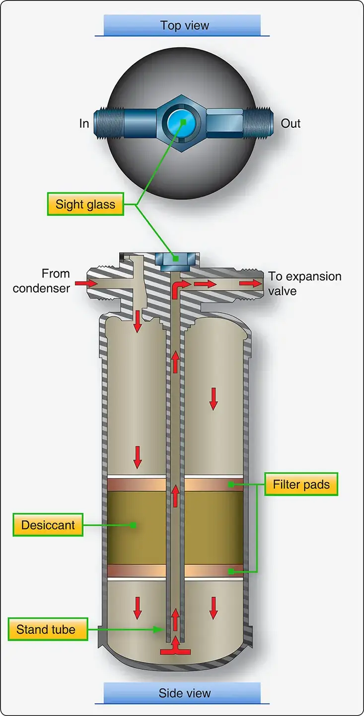 |
| Figure 2. A receiver dryer acts as reservoir and filter in a vapor cycle system. Bubbles viewed in the sight glass indicate the system is low on refrigerant and needs to be serviced |
Expansion Valve
Refrigerant exits the receiver dryer and flows to the expansion valve. The thermostatic expansion valve has an adjustable orifice through which the correct amount of refrigerant is metered to obtain optimal cooling. This is accomplished by monitoring the temperature of the gaseous refrigerant at the outlet of the next component in the cycle, the evaporator. Ideally, the expansion valve should only let the amount of refrigerant spray into the evaporator that can be completely converted to a vapor.
The temperature of the cabin air to be cooled determines the amount of refrigerant the expansion valve should spray into the evaporator. Only so much is needed to completely change the state of the refrigerant from a liquid to a vapor. Too little causes the gaseous refrigerant to be superheated by the time it exits the evaporator. This is inefficient. Changing the state of the refrigerant from liquid to vapor absorbs much more heat than adding heat to already converted vapor (superheat). The cabin air blowing over the evaporator will not be cooled sufficiently if superheated vapor is flowing through the evaporator. If too much refrigerant is released by the expansion valve into the evaporator, some of it remains liquid when it exits the evaporator. Since it next flows to the compressor, this could be dangerous. The compressor is designed to compress only vapor. If liquid is drawn in and attempts are made to compress it, the compressor could break, since liquids are essentially incompressible.
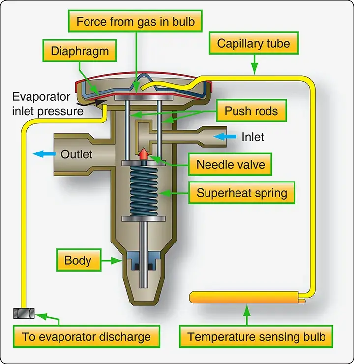
The temperature of superheated vapor is higher than liquid refrigerant that has not totally vaporized. A coiled capillary tube with a volatile substance inside is located at the evaporator outlet to sense this difference. Its internal pressure increases and decreases as temperature changes. The coiled end of the tube is closed and attached to the evaporator outlet. The other end terminates in the area above a pressure diaphragm in the expansion valve. When superheated refrigerant vapor reaches the coiled end of the tube, its elevated temperature increases the pressure inside the tube and in the space above the diaphragm. This increase in pressure causes the diaphragm to overcome spring tension in the valve. It positions a needle valve that increases the amount of refrigerant released by the valve. The quantity of refrigerant is increased so that the refrigerant only just evaporates, and the refrigerant vapor does not superheat.
When too much liquid refrigerant is released by the expansion valve, low-temperature liquid refrigerant arrives at the outlet of the evaporator. The result is low pressure inside the temperature bulb and above the expansion valve diaphragm. The superheat spring in the valve moves the needle valve toward the closed position, reducing the flow of refrigerant into the evaporator as the spring overcomes the lower pressure above the diaphragm. [Figure 3]
 |
| Figure 3. An internally equalized expansion valve |
Vapor cycle air conditioning systems that have large evaporators experience significant pressure drops while refrigerant is flowing through them. Externally equalized expansion valves use a pressure tap from the outlet of the evaporator to help the superheat spring balance the diaphragm. This type of expansion valve is easily recognizable by the additional small-diameter line that comes from the evaporator into the valve (2 total). Better control of the proper amount of refrigerant allowed through the valve is attained by considering both the temperature and pressure of the evaporator refrigerant. [Figure 4]
 |
| Figure 4. An externally equalized expansion valve uses the right rudder pedal. evaporator discharge temperature and pressure to regulate the amount of refrigerant passing through the valve and into the evaporator |
Evaporator
Most evaporators are constructed of copper or aluminum tubing coiled into a compact unit. Fins are attached to increase surface area, facilitating rapid heat transfer between the cabin air blown over the outside of the evaporator with a fan and the refrigerant inside. The expansion valve located at the evaporator inlet releases high-pressure, high-temperature liquid refrigerant into the evaporator. As the refrigerant absorbs heat from the cabin air, it changes into a low-pressure vapor. This is discharged from the evaporator outlet to the next component in the vapor cycle system, the compressor. The temperature and pressure pickups that regulate the expansion valve are located at the evaporator outlet.
The evaporator is situated in such a way that cabin air is pulled to it by a fan. The fan blows the air over the evaporator and discharges the cooled air back into the cabin. [Figure 5] This discharge can be direct when the evaporator is located in a cabin wall. A remotely located evaporator may require ducting from the cabin to the evaporator and from the evaporator back into the cabin. Sometimes the cool air produced may be introduced into an air distribution system where it can blow directly on the occupants through individual delivery vents. In this manner, the entire vapor cycle air conditioning system may be located fore or aft of the cabin. A multi-position fan switch controlled by the pilot is usually available. Figure 6 diagrams the vapor cycle air conditioning system in a Cessna Mustang very light jet. It has two evaporators that share in the cooling, with outlets integrated into a distribution system and cockpit mounted switches for the fans, as well as engaging and disengaging the system.
 |
| Figure 5. The evaporator of this aircraft’s vapor cycle air conditioning system is visible in the forward cabin sidewall behind the right rudder pedal |
 |
| Figure 6. The vapor cycle air conditioning system on a Cessna Mustang has two evaporators, one for the cockpit and one for the cabin. Each evaporator assembly contains the evaporator, a blower, a thermal expansion valve and the temperature feedback line from the outlet of the evaporator to the expansion valve |
When cabin air is cooled by flowing over the evaporator, it can no longer retain the water that it could at higher temperature. As a result, it condenses on the outside of the evaporator and needs to be collected and drained overboard. Pressurized aircraft may contain a valve in the evaporator drain line that opens only periodically to discharge the water, to maintain pressurization. Fins on the evaporator must be kept from being damaged, which could inhibit airflow. The continuous movement of warm cabin air around the fins keeps condensed water from freezing. Ice on the evaporator reduces the efficiency of the heat exchange to the refrigerant.
Compressor
The compressor is the heart of the vapor cycle air conditioning system. It circulates the refrigerant around the vapor cycle system. It receives low-pressure, low-temperature refrigerant vapor from the outlet of the evaporator and compresses it. As the pressure is increased, the temperature also increases. The refrigerant temperature is raised above that of the outside air temperature. The refrigerant then flows out of the compressor to the condenser where it gives off the heat to the outside air.
The compressor is the dividing point between the low side and the high side of the vapor cycle system. Often it is incorporated with fittings or has fittings in the connecting lines to it that are designed to service the system with refrigerant. Access to the low and high sides of the system are required for servicing, which can be accomplished with fitting upstream and downstream of the compressor.
Modern compressors are either engine driven or driven by an electric motor. Occasionally, a hydraulically driven compressor is used. A typical engine-driven compressor, similar to that found in an automobile, is located in the engine nacelle and operated by a drive belt off of the engine crankshaft. An electromagnetic clutch engages when cooling is required, which causes the compressor to operate. When cooling is sufficient, power to the clutch is cut, and the drive pulley rotates but the compressor does not. [Figure 7]
 |
| Figure 7. A typical belt drive engine driven compressor. The electromagnetic clutch pulley assembly in the front starts and stops the compressor depending on cooling demand |
Dedicated electric motor-driven compressors are also used on aircraft. Use of an electric motor allows the compressor to be located nearly anywhere on the aircraft, since wires can be run from the appropriate bus to the control panel and to the compressor. [Figure 8] Hydraulically driven compressors are also able to be remotely located. Hydraulic lines from the hydraulic manifold are run through a switch activated solenoid to the compressor. The solenoid allows fluid to the compressor or bypasses it. This controls the operation of the hydraulically driven compressor.
 |
| Figure 8. Examples of electric motor driven vapor cycle air conditioning compressors |
Regardless of how the vapor cycle air conditioning compressor is driven, it is usually a piston type pump. It requires use of a lightweight oil to lubricate and seal the unit. The oil is entrained by the refrigerant and circulates with it around the system. The crankcase of the compressor retains a supply of the oil, the level of which can be checked and adjusted by the technician. Valves exist on some compressor installations that can be closed to isolate the compressor from the remainder of the vapor cycle system while oil servicing takes place.
Condenser
The condenser is the final component in the vapor cycle. It is a radiator-like heat exchanger situated so that outside air flows over it and absorbs heat from the high-pressure, high temperature refrigerant received from the compressor. A fan is usually included to draw the air through the compressor during ground operation. On some aircraft, outside air is ducted to the compressor. On others, the condenser is lowered into the airstream from the fuselage via a hinged panel. Often, the panel is controlled by a switch on the throttle levers. It is set to retract the compressor and streamline the fuselage when full power is required. [Figure 9]
 |
| Figure 9. A vapor cycle air conditioning condenser assembly with an integral fan used to pull outside air through the unit during ground operation |
The outside air absorbs heat from the refrigerant flowing through the condenser. The heat loss causes the refrigerant to change state back into a liquid. The high-pressure liquid refrigerant then leaves the condenser and flows to the receiver dryer. A properly engineered system that is functioning normally fully condenses all the refrigerant flowing through the condenser.
Service Valves
All vapor cycle air conditioning systems are closed systems; however, access is required for servicing. This is accomplished through the use of two service valves. One valve is located in the high side of the system and the other in the low side. A common type of valve used on vapor cycle systems that operate with R12 refrigerant is the Schrader valve. It is similar to the valve used to inflate tires. [Figure 10] A central valve core seats and unseats by depressing a stem attached to it. A pin in the servicing hose fitting is designed to do this when screwed onto the valve’s exterior threads. All aircraft service valves should be capped when not in use.
 |
| Figure 10. Cross-section of an R12 refrigerant service valve |
R134a systems use valves that are very similar to the Schrader valve in function, operation, and location. As a safety device to prevent inadvertent mixing of refrigerants, R134a valve fittings are different from Schrader valve fittings and do not attach to Schrader valve threads. The R134a valve fittings are a quick-disconnect type.
Another type of valve called a compressor isolation valve is used on some aircraft. It serves two purposes. Like the Schrader valve, it permits servicing the system with refrigerant. It also can isolate the compressor so the oil level can be checked and replenished without opening the entire system and losing the refrigerant charge. These valves are usually hard mounted to the inlet and outlet of the compressor.
A compressor isolation valve has three positions. When fully open, it back seats and allows the normal flow of refrigerant in the vapor cycle. When fully closed or front seated, the valve isolates the compressor from the rest of the system and servicing with oil, or even replacement of the compressor, is possible without losing the refrigerant charge. When in an intermediate position, the valve allows access to the system for servicing. The system can be operated with the valve in this position, but should be back seated for normal operation. The valve handle and service port should be capped when servicing is complete. [Figure 11]
 |
| Figure 11. Compressor isolation valves isolate the compressor for maintenance or replacement. They also allow normal operation and servicing of the vapor cycle air conditioning system with refrigerant |
RELATED POSTS