The procedures and practices outlined in this site are general recommendations and are not intended to replace the manufacturer’s instructions in approved practices.
For the purpose of this discussion, a wire is described as a single solid conductor, or a stranded conductor, covered with an insulating material. [Figure 1]
 |
| Figure 1. Two types of aircraft wire |
The term “cable,” as used in aircraft electrical installations, includes the following:
- Multiconductor cable—two or more separately insulated conductors in the same jacket.
- Twisted pair—two or more separately insulated conductors twisted together.
- Shielded cable—one or more insulated conductors, covered with a metallic braided shield.
- Radio frequency cable—a single, insulated center conductor with a metallic braided outer conductor. The concentricity of the center conductor and the outer conductor is carefully controlled during manufacture to ensure that they are coaxial.
Wire Size
Wire is manufactured in sizes according to a standard known as the American wire gauge (AWG). The wire diameters become smaller as the gauge numbers become larger. The largest wire size shown in Figure 2 is number 0000, and the smallest is number 40. Larger and smaller sizes are manufactured but are not commonly used.
 |
| Figure 2. American wire gauge for standard annealed solid copper wire |
Wire size may be determined by using a wire gauge. [Figure 3] This type of gauge measures wires ranging in size from number 0 (zero) to number 36. The wire to be measured is inserted in the smallest slot that just accommodates the bare wire. The gauge number corresponding to that slot indicates the wire size. The slot has parallel sides and should not be confused with the semicircular opening at the end of the slot. The opening simply permits the free movement of the wire all the way through the slot.
 |
| Figure 3. Wire gauge |
Gauge numbers are useful in comparing the diameter of wires, but not all types of wire or cable can be accurately measured with a gauge. Large wires are usually stranded to increase their flexibility. In such cases, the total area can be determined by multiplying the area of one strand, usually computed in circular mils (commonly used as a reference to wire size) when diameter or gauge number is known by the number of strands in the wire or cable.
Factors Affecting the Selection of Wire Size
Several factors must be considered in selecting the size of wire for transmitting and distributing electric power. One factor is the allowable power loss (PR loss) in the line. This loss represents electrical energy converted into heat. The use of large conductors reduces the resistance and therefore the PR loss. However, large conductors are more expensive initially than small ones; they are heavier and require more substantial supports.
A second factor is the permissible voltage drop (IR drop) in the line. If the source maintains a constant voltage at the input to the line, any variation in the load on the line causes a variation in line current and a consequent variation in the IR drop in the line. A wide variation in the IR drop in the line causes poor voltage regulation at the load. The obvious remedy is to reduce either current or resistance. A reduction in load current lowers the amount of power being transmitted, whereas a reduction in line resistance increases the size and weight of conductors required. A compromise is generally reached whereby the voltage variation at the load is within tolerable limits and the weight of line conductors is not excessive.
A third factor is the current carrying ability of the conductor. When current is drawn through the conductor, heat is generated. The temperature of the wire rises until the heat radiated, or otherwise dissipated, is equal to the heat generated by the passage of current through the line. If the conductor is insulated, the heat generated in the conductor is not so readily removed as it would be if the conductor were not insulated. Thus, to protect the insulation from too much heat, the current through the conductor must be maintained below a certain value.
When electrical conductors are installed in locations where the ambient temperature is relatively high, the heat generated by external sources constitutes an appreciable part of the total conductor heating. Allowance must be made for the influence of external heating on the allowable conductor current, and each case has its own specific limitations. The maximum allowable operating temperature of insulated conductors varies with the type of conductor insulation being used.
Tables are available that list the safe current ratings for various sizes and types of conductors covered with various types of insulation. The chart in Figure 4 shows the current carrying capacity and resistance of copper wire continuous duty wire in bundles at various temperature ratings.
 |
| Figure 4. Current-carrying capacity and resistance of copper wire |
Factors Affecting Selection of Conductor Material
Although silver is the best conductor, its cost limits its use to special circuits where a substance with high conductivity is needed. The two most generally used conductors are copper and aluminum. Each has characteristics that make its use advantageous under certain circumstances; also, each has certain disadvantages.
Copper has a higher conductivity; it is more ductile, can be drawn out, has relatively high tensile strength, and can be easily soldered. It is more expensive and heavier than aluminum.
Although aluminum has only about 60 percent of the conductivity of copper, it is used extensively. Its light weight makes possible long spans, and its relatively large diameter for a given conductivity reduces corona, the discharge of electricity from the wire when it has a high potential. The discharge is greater when smaller diameter wire is used than when larger diameter wire is used. Some bus bars are made of aluminum which has a greater radiating surface than copper for the same conductance. The characteristics of copper and aluminum are compared in Figure 5.
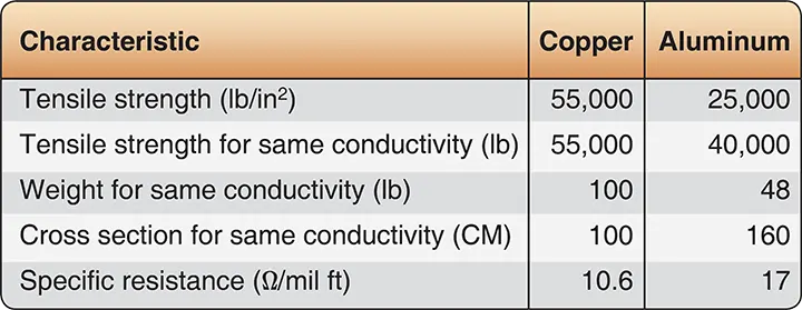 |
| Figure 5. Characteristics of copper and aluminum |
Voltage Drop in Aircraft Wire and Cable
The voltage drop in the main power cables from the aircraft generation source or the battery to the bus should not exceed 2 percent of the regulated voltage when the generator is carrying rated current or the battery is being discharged at a 5-minute rate. The 5-minute rate in this case means that the battery should last a minimum of 5 minutes in an emergency, with all battery operated equipment running. Figure 6 shows the recommended maximum voltage drop in the load circuits between the bus and the utilization equipment.
 |
| Figure 6. Recommended voltage drop in load circuits |
The resistance of the current return path through the aircraft structure is always considered negligible. However, this is based on the assumption that adequate bonding of the structure or a special electric current return path has been provided that is capable of carrying the required electric current with a negligible voltage drop. A resistance measurement of 0.005 ohms from ground point of the generator or battery to ground terminal of any electrical device is considered satisfactory.
Another satisfactory method of determining circuit resistance is to check the voltage drop across the circuit. If the voltage drop does not exceed the limit established by the aircraft or product manufacturer, the resistance value for the circuit is considered satisfactory. When using the voltage drop method of checking a circuit, the input voltage must be maintained at a constant value.
The graph in Figure 7 applies to copper conductors carrying direct current. To select the correct size of conductor, two major requirements must be met. First, the size must be sufficient to prevent an excessive voltage drop while carrying the required current over the required distance. Second, the size must be sufficient to prevent overheating of the cable while carrying the required current. The graphs in Figures 7 and 8 can simplify these determinations.
 |
| Figure 7. Conductor graph-continuous flow |
 |
| Figure 8. Conductor graph—intermittent flow |
To use this graph to select the proper size of conductor, the following must be known:
- The conductor length in feet
- The number of amperes of current to be carried
- The amount of voltage drop permitted
- Whether the current to be carried is intermittent or continuous
- The estimated or measured temperature of the conductor
- Whether the wire to be installed is in a conduit or in a bundle
- Whether it is a single conductor in free air
Suppose that you want to install a 50-foot conductor from the aircraft bus to the equipment in a 28-volt system. For this length, a 1-volt drop is permissible for continuous operation with a conductor temperature of 20 ºC or less. By referring to the chart in Figure 7, the maximum number of feet a conductor may be run carrying a specified current with a 1-volt drop can be determined. In this example, the number 50 is selected.
Assuming the current required by the equipment is 20 amperes, the line indicating the value of 20 amperes should be selected from the diagonal lines. Follow this diagonal line downward until it intersects the horizontal line number 50. From this point, drop straight down to the bottom of the graph to find that a conductor between size No. 8 and No. 10 is required to prevent a greater drop than 1 volt. Since the indicated value is between two numbers, the larger size, No. 8, should be selected. This is the smallest size that should be used to avoid an excessive voltage drop.
If the installation is for equipment having only an intermittent (maximum 2 minutes) requirement for power, the graph in Figure 8 is used in the same manner.
Conductor Insulation
Two fundamental properties of insulation materials (e.g., rubber, glass, asbestos, and plastic) are insulation resistance and dielectric strength. These are entirely different and distinct properties.
Insulation resistance is the resistance to current leakage through and over the surface of insulation materials. Insulation resistance can be measured with a megger without damaging the insulation. This serves as a useful guide in determining the general condition of insulation. However, the data obtained in this manner may not give a true picture of the condition of the insulation. Clean, dry insulation having cracks or other faults may show a high value of insulation resistance but would not be suitable for use.
Dielectric strength is the ability of the insulator to withstand potential difference and is usually expressed in terms of the voltage at which the insulation fails due to electrostatic stress. Maximum dielectric strength values can be measured by raising the voltage of a test sample until the insulation breaks down.
Because of the expense of insulation, its stiffening effect, and the great variety of physical and electrical conditions under which the conductors are operated, only the necessary minimum insulation is applied for any particular type of cable designed to do a specific job.
The type of conductor insulation material varies with the type of installation. Rubber, silk, and paper insulation are no longer used extensively in aircraft systems. More common today are such materials as vinyl, cotton, nylon, Teflon, and Rockbestos.
Identifying Wire and Cable
To aid in testing and repair operations, many maintenance activities mark wire or cable with a combination of letters and numbers that identify the wire, the circuit it belongs to, the gauge number, and other information necessary to relate the wire or cable to a wiring diagram. Such markings are the identification code.
There is no standard procedure for marking and identifying wiring; each manufacturer normally develops its own identification code. Figure 9 illustrates one identification system and shows the usual spacing in marking a wire. Some system components, especially plugs and jacks, are identified by a letter or group of letters and numbers added to the basic identification number. These letters and numbers may indicate the location of the component in the system. Interconnected cables are also marked in some systems to indicate location, proper termination, and use. In any system, the marking should be legible, and the stamping color should contrast with the color of the wire insulation. For example, use black stamping with light-colored backgrounds, or white stamping on dark-colored backgrounds.
 |
| Figure 9. Spacing of printed identification marks |
Most manufacturers mark the wires at intervals of not more than 15 inches lengthwise and within 3 inches of each junction or terminating point. [Figure 10]
 |
| Figure 10. Wire identification at a terminal block |
Coaxial cable and wires at terminal blocks and junction boxes are often identified by marking or stamping a wiring sleeve rather than the wire itself. For general purpose wiring, flexible vinyl sleeving, either clear or white opaque, is commonly used. For high-temperature applications, silicone rubber or silicone fiberglass sleeving is recommended. Where resistance to synthetic hydraulic fluids or other solvents is necessary, either clear or white opaque nylon sleeving can be used.
While the preferred method is to stamp the identification marking directly on the wire or on sleeving, other methods are often employed. One method uses a marked sleeve tied in place. The other uses a pressure-sensitive tape. [Figure 11]
 |
| Figure 11. Alternate methods of identifying wire bundles |
Electrical Wiring Installation
The following recommended procedures for installing aircraft electrical wiring are typical of those used on most types of aircraft. For purposes of this discussion, the following definitions are applicable:
- Open wiring—any wire, wire group, or wire bundle not enclosed in conduit.
- Wire group—two or more wires in the same location, tied together to identity the group.
- Wire bundle—two or more wire groups tied together because they are going in the same direction at the point where the tie is located. The bundle facilitates maintenance.
- Electrically protected wiring—wires that include in the circuit protections against overloading, such as fuses, circuit breakers, or other limiting devices.
- Electrically unprotected wiring—wires, generally from generators to main bus distribution points, that do not have protection, such as fuses, circuit breakers, or other current-limiting devices.
Wire Groups and Bundles
Grouping or bundling certain wires, such as electrically unprotected power wiring and wiring to duplicate vital equipment, should be avoided. Wire bundles should generally be limited in size to a bundle of 75 wires, or 2 inches in diameter where practicable. When several wires are grouped at junction boxes, terminal blocks, panels, etc., the identity of the group within a bundle can be retained. [Figure 12]
 |
| Figure 12. Group and bundle ties |
When specified on the engineering drawing, parallel wires must be twisted. The most common examples are:
- Wiring in the vicinity of magnetic compass or flux valve,
- Three-phase distribution wiring, and
- Certain other wires (usually radio wiring).
Twist the wires so that they lie snugly against each other, making approximately the number of twists per foot as listed in Figure 13. Always check wire insulation for damage after twisting. If the insulation is torn or frayed, replace the wire.
 |
| Figure 13. Recommended number of twists per foot |
Spliced Connections in Wire Bundles
Spliced connections in wire groups or bundles should be located so that they can be easily inspected. Splices should also be staggered so that the bundle does not become excessively enlarged. [Figure 14] All noninsulated splices should be covered with plastic, securely tied at both ends.
 |
| Figure 14. Staggered splices in wire bundle |
Slack in Wiring Bundles
Single wires or wire bundles should not be installed with excessive slack. Slack between supports should normally not exceed ½ inch. This is the maximum it should be possible to deflect the wire with normal hand force. However, this may be exceeded if the wire bundle is thin and the clamps are far apart. But the slack should never be so great that the wire bundle can abrade against any surface it touches. [Figure 15]
 |
| Figure 15. Slack in wire bundle between supports |
A sufficient amount of slack should be allowed near each end of a bundle to:
- Permit easy maintenance;
- Allow replacement of terminals;
- Relieve mechanical strain on the wires, wire junctions, or supports;
- Permit free movement of shock and vibration-mounted equipment; and
- Permit shifting of equipment for purposes of maintenance.
Bend Radii
Bends in wire groups or bundles should not be less than ten times the outside diameter of the wire group or bundle. However, at terminal strips, where wire is suitably supported at each end of the bend, a minimum radius of three times the outside diameter of the wire, or wire bundle, is usually acceptable. There are exceptions to these guidelines in the case of certain types of cable; for example, coaxial cable should never be bent to a smaller radius than six times the outside diameter.
Routing and Installation
All wiring should be installed so that it is mechanically and electrically sound and neat in appearance. Whenever practicable, wires and bundles should be routed parallel with, or at right angles to, the stringers or ribs of the area involved. An exception to this general rule is the coaxial cables, which are routed as directly as possible.
The wiring must be adequately supported throughout its length. A sufficient number of supports must be provided to prevent undue vibration of the unsupported lengths. All wires and wire groups should be routed and installed to protect them from:
- Chafing or abrasion;
- High temperature;
- Being used as handholds, or as support for personal belongings and equipment;
- Damage by personnel moving within the aircraft;
- Damage from cargo stowage or shifting;
- Damage from battery acid fumes, spray, or spillage; and
- Damage from solvents and fluids.
Protection Against Chafing
Wires and wire groups should be installed so that they are protected against chafing or abrasion in those locations where contact with sharp surfaces or other wires would damage the insulation. Damage to the insulation can cause short circuits, malfunctions, or inadvertent operation of equipment. Cable clamps should be used to support wire bundles at each hole through a bulkhead. [Figure 16] If wires come closer than ¼ inch to the edge of the hole, a suitable grommet is used in the hole. [Figure 17]
 |
| Figure 16. Cable clamp at bulkhead hole |
 |
| Figure 17. Cable clamp and grommet at bulkhead hole |
Sometimes, it is necessary to cut nylon or rubber grommets to facilitate installation. In these instances, after insertion, the grommet can be secured in place with general purpose cement. The slot should be at the top of the hole, and the cut should be made at an angle of 45° to the axis of the wire bundle hole.
Protection Against High Temperature
To prevent insulation deterioration, wires should be kept separate from high-temperature equipment, such as resistors, exhaust stacks, heating ducts. The amount of separation is usually specified by engineering drawings. Some wires must be run through hot areas. These wires must be insulated with high-temperature rated material, such as asbestos, fiberglass, or Teflon. Additional protection is also often required in the form of conduits. A low-temperature insulated wire should never be used to replace a high-temperature insulated wire.
Many coaxial cables have soft plastic insulation, such as polyethylene, that is especially subject to deformation and deterioration at elevated temperatures. All high-temperature areas should be avoided when installing these cables.
Additional abrasion protection should be given to asbestos wires enclosed in conduit. Either conduit with a high temperature rubber liner should be used or asbestos wires can be enclosed individually in high-temperature plastic tubes before being installed in the conduit.
Protection Against Solvents and Fluids
Avoid installing wires in areas where they are subjected to damage from fluids. Wires should not be placed in the lowest four inches of the aircraft fuselage, except those that must terminate in that area. If there is a possibility that wiring without a protective nylon outer jacket may be soaked with fluids, plastic tubing should be used to protect it. This tubing should extend past the exposure area in both directions and should be tied at each end. If the wire has a low point between the tubing ends, provide a 1⁄8-inch drainage hole. [Figure 18] This hole should be punched into the tubing after the installation is complete and the low point definitely established by using a hole punch to cut a half circle. Care should be taken not to damage any wires inside the tubing when using the punch.
 |
| Figure 18. Drainage hole in low point of tubing |
Wire should never be routed below a battery. All wires in the vicinity of a battery should be inspected frequently. Wires discolored by battery fumes should be replaced.
Protection of Wires in Wheel Well Area
Wires located in wheel wells are subject to many additional hazards, such as exposure to fluids, pinching, and severe flexing in service. All wire bundles should be protected by sleeves of flexible tubing securely held at each end. There should be no relative movement at points where flexible tubing is secured. These wires and the insulating tubing should be inspected carefully at very frequent intervals, and wires or tubing should be replaced at the first sign of wear. There should be no strain on attachments when parts are fully extended, but slack should not be excessive.
Routing Precautions
When wiring must be routed parallel to combustible fluid or oxygen lines for short distances, as much separation as possible should be maintained. The wires should be on a level with, or above, the plumbing lines. Clamps should be spaced so that if a wire is broken at a clamp, it will not contact the line. Where a 6-inch separation is not possible, both the wire bundle and the plumbing line can be clamped to the same structure to prevent any relative motion. If the separation is less than 2 inches but more than 1⁄2 inch, two cable clamps back to back can be used to maintain a rigid separation only and not for support of the bundle. [Figure 19] No wire should be routed so that it is located nearer than ½ inch to a plumbing line, nor should a wire or wire bundle be supported from a plumbing line that carries flammable fluids or oxygen.
 |
| Figure 19. Separation of wires from plumbing lines |
Wiring should be routed to maintain a minimum clearance of at least 3 inches from control cables. If this cannot be accomplished, mechanical guards should be installed to prevent contact between wiring and control cables.
Installation of Cable Clamps
Cable clamps should be installed with regard to the proper mounting angle. [Figure 20]
 |
| Figure 20. Proper mounting angle for cable clamps |
The mounting screw should be above the wire bundle. It is also desirable that the back of the cable clamp rest against a structural member where practicable. Figure 21 shows some typical mounting hardware used in installing cable clamps. Be sure that wires are not pinched in cable clamps.
 |
| Figure 21. Typical mounting hardware for cable clamps |
Where possible, mount them directly to structural members. [Figure 22]
 |
| Figure 22. Mounting cable clamps to structure |
Clamps can be used with rubber cushions to secure wire bundles to tubular structures. [Figure 23] Such clamps must fit tightly but should not be deformed when locked in place.
 |
| Figure 23. Installing cable clamps to tubular structure |