Connectors
Connectors (plugs and receptacles) facilitate maintenance when frequent disconnection is required. Since the cable is soldered to the connector inserts, the joints should be individually installed and the cable bundle firmly supported to avoid damage by vibration. Connectors have been particularly vulnerable to corrosion in the past, due to condensation within the shell. Special connectors with waterproof features have been developed that may replace nonwaterproof plugs in areas where moisture causes a problem. A connector of the same basic type and design should be used when replacing a connector. Connectors that are susceptible to corrosion difficulties may be treated with a chemically inert waterproof jelly. When replacing connector assemblies, the socket-type insert should be used on the half that is “ live” or “hot” after the connector is disconnected to prevent unintentional grounding.
Types of Connectors
The manufacturer’s variations are differences in appearance and in the method of meeting a specification. Some commonly used connectors are shown in Figure 1.
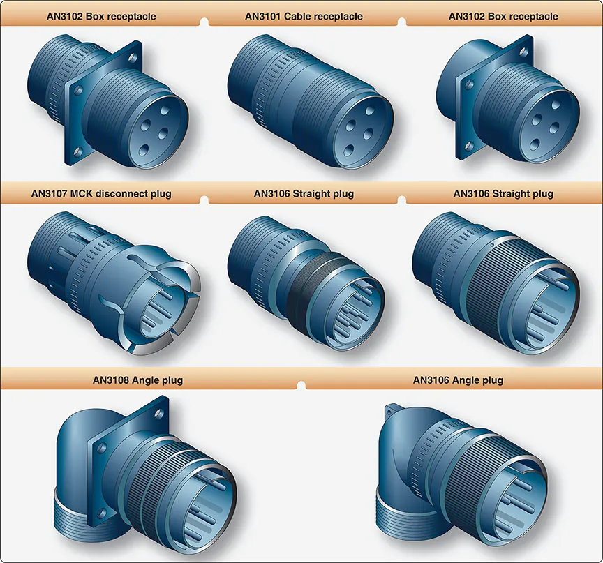 |
| Figure 1. AN connectors |
There are five basic classes of AN connectors used in most aircraft. Each class of connector has slightly different construction characteristics. Classes A, B, C, and D are made of aluminum, and class K is made of steel.
- Class A—solid, one-piece back shell general-purpose connector.Class B—connector back shell separates into two parts lengthwise. Used primarily where it is important that the soldered connectors are readily accessible. The back shell is held together by a threaded ring or by screws.
- Class C—a pressurized connector with inserts that are not removable. Similar to a class A connector in appearance, but the inside sealing arrangement is sometimes different. It is used on walls or bulkheads of pressurized equipment.
- Class D—moisture and vibration resistant connector that has a sealing grommet in the back shell. Wires are threaded through tight fitting holes in the grommet, sealing against moisture.
- Class K—a fireproof connector used in areas where it is vital that the electric current is not interrupted, even though the connector may be exposed to continuous open flame. Wires are crimped to the pin or socket contacts and the shells are made of steel. This class of connector is normally longer than other connectors.
Connector Identification
Code letters and numbers are marked on the coupling ring or shell to identify a connector. This code provides all the information necessary to obtain the correct replacement for a defective or damaged part. [Figure 2]
 |
| Figure 2. AN connector markings |
Many special-purpose connectors have been designed for use in aircraft applications. These include subminiature and rectangular shell connectors, and connectors with short body shells, or of split-shell construction.
RELATED POSTS
Installation of Connectors
The following procedures outline one recommended method of assembling connectors to receptacles:
- Locate the proper position of the plug in relation to the receptacle by aligning the key of one part with the groove or keyway of the other part.
- Start the plug into the receptacle with a slight forward pressure and engage the threads of the coupling ring and receptacle.
- Alternately push in the plug and tighten the coupling ring until the plug is completely seated.
- Use connector pliers to tighten coupling rings one-sixteenth to one-eighth turn beyond finger tight if space around the connector is too small to obtain a good finger grip.
- Never use force to mate connectors to receptacles.
Do not hammer a plug into its receptacle and never use a torque wrench or pliers to lock coupling rings.
A connector is generally disassembled from a receptacle in the following manner:
- Use connector pliers to loosen coupling rings that are too tight to be loosened by hand.
- Alternately pull on the plug body and unscrew the coupling ring until the connector is separated.
- Protect disconnected plugs and receptacles with caps or plastic bags to keep debris from entering and causing faults.
- Do not use excessive force and do not pull on attached wires.
Conduit
Conduit is used in aircraft installations for the mechanical protection of wires and cables. It is available in metallic and nonmetallic materials and in both rigid and flexible form.
When selecting conduit size for a specific cable bundle application, it is common practice to allow for ease in maintenance and possible future circuit expansion by specifying the conduit inner diameter about 25 percent larger than the maximum diameter of the conductor bundle. The nominal diameter of a rigid metallic conduit is the outside diameter. Therefore, to obtain the inside diameter, subtract twice the tube wall thickness.
From the abrasion standpoint, the conductor is vulnerable at the ends of the conduit. Suitable fittings are affixed to conduit ends in such a manner that a smooth surface comes in contact with the conductor within the conduit. When fittings are not used, the conduit end should be flared to prevent wire insulation damage. The conduit is supported by clamps along the conduit run.
Many of the common conduit installation problems can be avoided by proper attention to the following details:
- Do not locate conduit where it can be used as a handhold or footstep.
- Provide drain holes at the lowest point in a conduit run. Drilling burrs should be carefully removed from the drain holes.
- Support the conduit to prevent chafing against the structure and to avoid stressing its end fittings.
Damaged conduit sections should be repaired to prevent injury to the wires or wire bundle. The minimum acceptable tube bend radii for rigid conduit as prescribed by the manufacturer’s instructions should be carefully followed. Kinked or wrinkled bends in a rigid conduit are normally not considered acceptable.
Flexible aluminum conduit is widely available in two types: bare flexible and rubber-covered conduit. Flexible brass conduit is normally used instead of flexible aluminum where it is necessary to minimize radio interference. Flexible conduit may be used where it is impractical to use rigid conduit, such as areas that have motion between conduit ends or where complex bends are necessary. Transparent adhesive tape is recommended when cutting flexible conduit with a hacksaw to minimize fraying of the braid.