Proper wire and cable preparation is essential when maintaining engine ignition and electrical systems. Electrical connections must be correctly prepared to ensure reliable current flow, mechanical strength, and resistance to vibration. Cutting, stripping, crimping, and splicing procedures require the correct tools and techniques to prevent conductor damage and connection failures.
Cutting Wire and Cable
To make installation, maintenance, and repair easier, runs of wire and cable in aircraft are broken at specified locations by junctions, such as connectors, terminal blocks, or buses. Before assembly to these junctions, wires and cables must be cut to length.
All wires and cables should be cut to the lengths specified on drawings and wiring diagrams. The cut should be made clean and square, and the wire or cable should not be deformed. If necessary, large diameter wire should be reshaped after cutting. Good cuts can be made only if the blades of cutting tools are sharp and free from nicks. A dull blade deforms and extrudes wire ends.
Stripping Wire and Cable
Nearly all wire and cable used as electrical conductors are covered with some type of insulation. In order to make electrical connections with the wire, a part of this insulation must be removed to expose the bare conductor. Copper wire can be stripped in a number of ways, depending on the size and insulation.
Figure 1 lists some types of stripping tools recommended for various wire sizes and types of insulation.
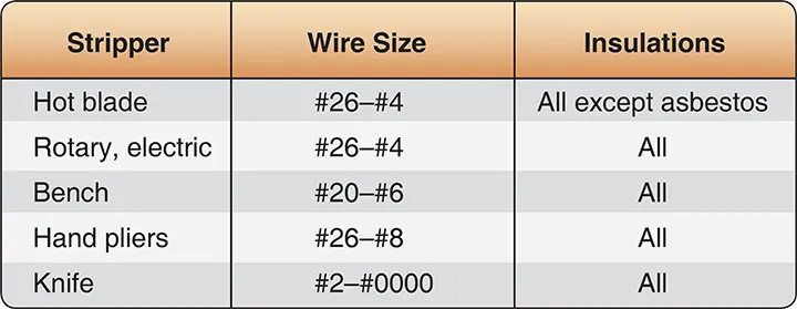 |
| Figure 1. Wire strippers for copper wire |
Aluminum wire must be stripped using extreme care, since individual strands break very easily after being nicked.
The following general precautions are recommended when stripping any type of wire:
- When using any type of wire stripper, hold the wire so that it is perpendicular to the cutting blades.
- Adjust automatic stripping tools carefully; follow the manufacturer’s instructions to avoid nicking, cutting, or otherwise damaging strands. This is especially important for aluminum wires and for copper wires smaller than No. 10. Examine stripped wires for damage. Cut off and restrip, if length is sufficient, or reject and replace any wires with more than the allowable number of nicked or broken strands listed in the manufacturer’s instructions.
- Make sure the insulation is cleanly cut, with no frayed or ragged edges. Trim, if necessary.
- Make sure all insulation is removed from the stripped area. Some types of wires are supplied with a transparent layer of insulation between the conductor and the primary insulation. If this is present, remove it.
- When using hand wire strippers to remove lengths of insulation longer than 3⁄4 inch, the stripping process is easier to accomplish in two or more operations.
- Retwist copper strands by hand or with pliers, if necessary, to restore natural lay and tightness of strands.
A pair of hand wire strippers is shown in Figure 2. This tool is commonly used to strip most types of wire.
 |
| Figure 2. Light duty hand wire strippers |
The following general procedures describe the steps for stripping wire with a hand stripper. [Figure 3]
- Insert the wire into the exact center of the correct cutting slot for the wire size being stripped. Each slot is marked with wire size.
- Close handles together as far as they will go.
- Release the handles, allowing the wire holder to return to the open position.
- Remove stripped wire.
 |
| Figure 3. Stripping wire with hand strippers |
Solderless Terminals and Splices
Splicing of electrical cable should be kept to a minimum and avoided entirely in locations subject to extreme vibrations. Individual wires in a group or bundle can usually be spliced if the completed splice is located where it can be inspected periodically. The splices should be staggered so that the bundle does not become excessively enlarged.
Many types of aircraft splice connectors are available for splicing individual wires. Self-insulated splice connectors are usually preferred; however, a noninsulated splice connector can be used if the splice is covered with plastic sleeving secured at both ends. Solder splices may be used, but they are particularly brittle and not recommended.
Electric wires are terminated with solderless terminal lugs to permit easy and efficient connection to and disconnection from terminal blocks, bus bars, or other electrical equipment. Solderless splices join electric wires to form permanent continuous runs. Solderless terminal lugs and splices are made of copper or aluminum and are preinsulated or uninsulated, depending on the desired application.
Terminal lugs are generally available in three types for use in different space conditions. These are the flag, straight, and right-angle lugs. Terminal lugs are crimped, sometimes called staked or swaged, to the wires by means of hand or power crimping tools.
Copper Wire Terminals
Copper wires are terminated with solderless, preinsulated straight copper terminal lugs. The insulation is part of the terminal lug and extends beyond its barrel so that it covers a portion of the wire insulation, making the use of an insulation sleeve unnecessary. [Figure 4]
 |
| Figure 4. Preinsulated terminal lug |
In addition, preinsulated terminal lugs contain an insulation grip (a metal reinforcing sleeve) beneath the insulation for extra gripping strength on the wire insulation. Preinsulated terminals accommodate more than one size of wire; the insulation is usually color coded to identify the wire sizes that can be terminated with each of the terminal lug sizes.
Crimping Tools
Hand, portable power, and stationary power tools are available for crimping terminal lugs. These tools crimp the barrel of the terminal lug to the conductor and simultaneously crimp the insulation grip to the wire insulation.
Hand crimping tools all have a self-locking ratchet that prevents opening the tool until the crimp is complete. Some hand crimping tools are equipped with a nest of various-sized inserts to fit different size terminal lugs. Others are used on one terminal lug size only. All types of hand crimping tools are checked by gauges for proper adjustment of crimping jaws.
Figure 5 shows a terminal lug inserted into a hand tool.
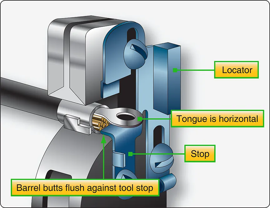 |
| Figure 5. Inserting terminal lug into hand tool |
The following general guidelines outline the crimping procedure:
- Strip the wire insulation to proper length.
- Insert the terminal lug, tongue first, into the hand tool barrel crimping jaws until the terminal lug barrel butts flush against the tool stop.
- Insert the stripped wire into the terminal lug barrel until the wire insulation butts flush against the end of the barrel.
- Squeeze the tool handles until the ratchet releases.
- Remove the completed assembly and examine it for proper crimp.
Some types of uninsulated terminal lugs are insulated after assembly to a wire by means of pieces of transparent flexible tubing called sleeves. The sleeve provides electrical and mechanical protection at the connection. When the sleeve fits tightly over the terminal lug, it need not be tied; otherwise, it should be secured with lacing cord. [Figure 6]
 |
| Figure 6. Insulating sleeves |
Aluminum Wire Terminals
Aluminum wire is being used increasingly in aircraft systems because of its weight advantage over copper. However, bending aluminum causes “work hardening” of the metal, making it brittle. This results in failure or breakage of strands much sooner than in a similar case with copper wire. Aluminum also forms a high-resistance oxide film immediately upon exposure to air. To compensate for these disadvantages, it is important to use the most reliable installation procedures. Only aluminum terminal lugs are used to terminate aluminum wires.
All aluminum terminals incorporate an inspection hole that permits checking the depth of wire insertion. [Figure 7]
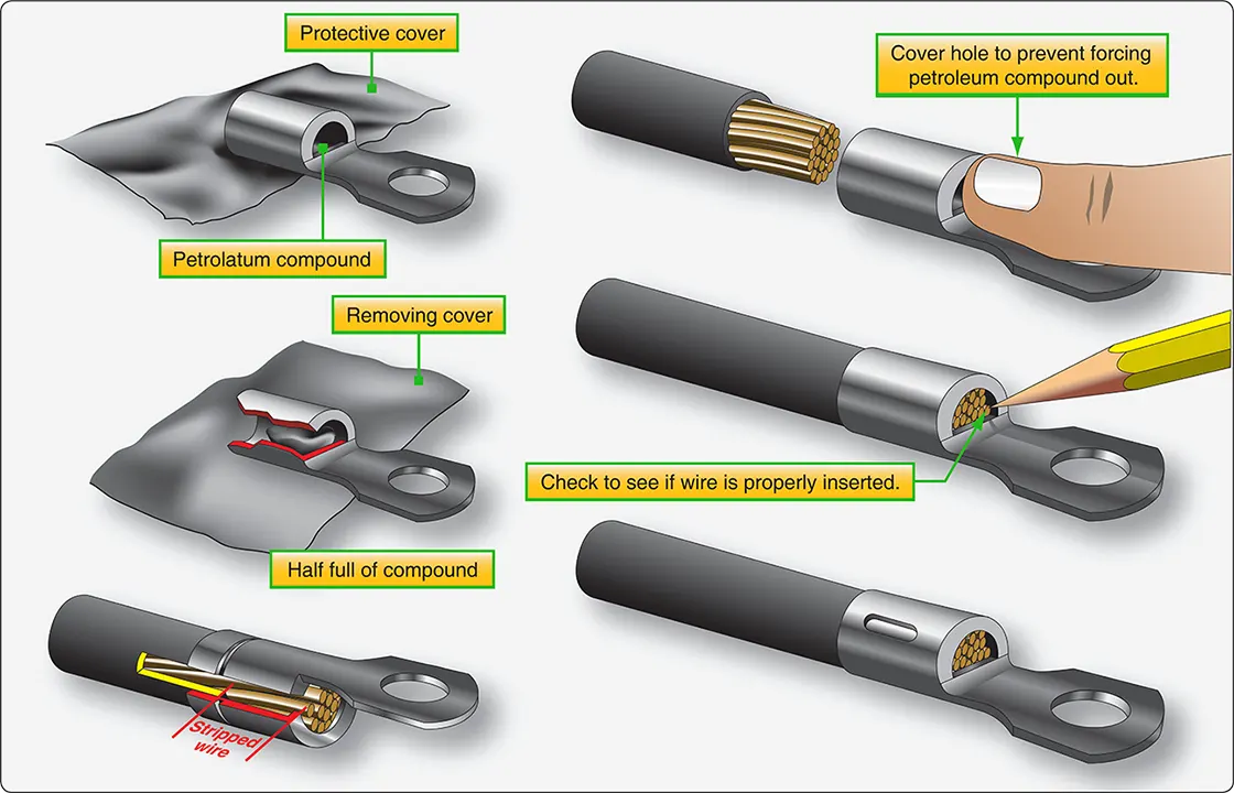 |
| Figure 7. Inserting aluminum wire into aluminum terminal lugs |
The barrel of aluminum terminal lugs is filled with a petrolatum-zinc dust compound. This compound removes the oxide film from the aluminum by a grinding process during the crimping operation. The compound also minimizes later oxidation of the completed connection by excluding moisture and air. The compound is retained inside the terminal lug barrel by a plastic or foil seal at the end of the barrel.
Splicing Copper Wires Using Preinsulated Splices
Preinsulated permanent copper splices join small wires of sizes 22 through 10. Each splice size can be used for more than one wire size. Splices are usually color coded in the same manner as preinsulated, small copper terminal lugs. Some splices are insulated with white plastic. Splices are also used to reduce wire sizes. [Figure 8]
 |
| Figure 8. Reducing wire size with a permanent splice |
Crimping tools are used to accomplish this type of splice. The crimping procedures are the same as those used for terminal lugs, except that the crimping operation must be done twice, one for each end of the splice.