Oxy-fuel welding and cutting require a combination of properly matched gases, regulators, hoses, torches, and safety equipment. Correct selection and setup of this equipment are essential for safe operation and for producing a clean, efficient flame.
Welding Gases
Acetylene
Acetylene is the primary fuel gas used for oxy-fuel welding and cutting. It is chemically very unstable, and is stored in special cylinders designed to keep the gas dissolved. The cylinders are packed with a porous material and then saturated with acetone. When the acetylene is added to the cylinder, it dissolves; in this solution, it becomes stable. Pure acetylene stored in a free state explodes from a slight shock at 29.4 pounds per square inch (psi). The acetylene pressure gauge should never be set higher than 15 psi for welding or cutting.
Argon
Argon is a colorless, odorless, tasteless, and non-toxic inert gas. An inert gas cannot readily combine with other elements. It has a very low chemical reactivity and low thermal conductivity. It is used as a gas shield for the electrode in MIG, TIG, and plasma welding equipment.
Helium
Helium is a colorless, odorless, tasteless, and non-toxic inert gas. Its boiling and melting points are the lowest of the elements and it normally exists only in gas form. It is used as a protective gas shield for many industrial uses including electric arc welding.
Hydrogen
Hydrogen is a colorless, odorless, tasteless, and highly flammable gas. It can be used at a higher pressure than acetylene and is used for underwater welding and cutting. It also can be used for aluminum welding using the oxy-hydrogen process.
Oxygen
Oxygen is a colorless, odorless, and nonflammable gas. It is used in the welding process to increase the rate of combustion, thereby raising the flame temperature of the fuel gas.
Pressure Regulators
A pressure regulator is attached to a gas cylinder and is used to lower the cylinder pressure to the desired working pressure. Regulators have two gauges, one indicating the pressure in the cylinder and the second showing the working pressure. By turning the adjustment knob in or out, a spring operating a flexible diaphragm opens or closes a valve in the regulator. Turning the knob in causes the flow and pressure to increase; backing it out decreases the flow and pressure.
There are two types of regulators: single-stage and two-stage regulators. They perform the same function but the two-stage regulator maintains a more constant outlet pressure and flow as the cylinder volume and pressure drops. Two-stage regulators can be identified by a larger, second pressure chamber under the regulator knob. [Figures 1 and 2]
 |
| Figure 1. Single-stage acetylene regulator. Note the maximum 15-psi working pressure. The notched groove cylinder connection nut indicates a left-hand thread |
 |
| Figure 2. Two-stage oxygen regulator. No groove on the cylinder connection nut indicates a right-hand thread |
Welding Hose
A welding hose connects the regulators to the torch. It is typically a double hose joined together during manufacture. The acetylene hose is red and has left-hand threads indicated by a groove cut into the connection nut. The oxygen hose is green and has right hand threads indicated by the absence of a groove on the connection nut.
Welding hoses are produced in different sizes from ¼ inch to ½ inch inside diameter (ID). The hose should be marked for light, standard, and heavy duty service plus a grade indicating whether it has an oil-resistant and/or flame-resistant cover. The hose should have the date of manufacture, maximum working pressure of 200 psi, and indicate that it meets specification IP-90 of the Rubber Manufacturers Association and the Compressed Gas Association for rubber welding hoses. Grade-R hose should only be used with acetylene gas. A T-grade hose must be used with propane, MAPP®, propylene, and other fuel gases.
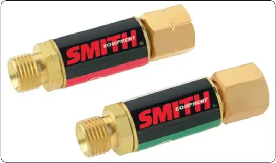
Check Valves and Flashback Arrestors
The check valve prevents reverse gas flow and can be installed either between the regulator and the hose or between the hose and the torch. [Figure 3] Excessive overheating of cutting, welding, and heating tips can cause flashback conditions. A flashback can be caused when a tip is overheated and the gas ignites before passing out of the tip. The flame is then burning internally rather than on the outside of the tip and is usually identified by a shrill hissing or squealing noise.
 |
| Figure 3. Check valves |
A flashback arrestor installed on each hose prevents a high pressure flame or oxygen-fuel mixture from being pushed back into either cylinder causing an explosion. The flashback arrestors incorporate a check valve that stops the reverse flow of gas and the advancement of a flashback fire. [Figure 4]
 |
| Figure 4. Flashback arrestors |
Torches
Equal Pressure Torch
The equal pressure torch is the most commonly used torch for oxy-acetylene welding. It has a mixing chamber and uses acetylene fuel at 1 to 15 psi. The flame is easy to adjust and there is less chance of flashback with this torch. There are several small lightweight torches of this type that are ideal for aviation welding projects. The Smith Airline™ and the Meco Midget™ torches are small enough to be used in close confined areas, lightweight enough to reduce fatigue during long welding sessions yet with the appropriate tips are capable of welding steel up to 0.250 inch thick.
Injector Torch
The injector torch uses fuel gas at pressures between just above 0 and 2 psi. This torch is typically used with propane and propylene gas. High-pressure oxygen comes through a small nozzle inside the torch head and pulls the fuel gas along with it via a venturi effect. The low-pressure injector torch is more prone to flashback.
Cutting Torch
The cutting torch is an attachment added to the torch handle that allows the cutting of metal. The cutting process is fundamentally the rapid burning or oxidizing of the metal in a localized area. The metal is heated to a bright red color (approximately 1,400 °F to 1,600 °F), which is the kindling temperature, using only the preheat jets. Then, a jet of high-pressure oxygen released by the lever on the cutting attachment is directed against the heated metal. This oxygen blast combines with the hot metal and forms an intensely hot oxide. The molten oxide is blown down the sides of the cut, heating the metal in its path to the kindling temperature as the torch is moved along the line of the desired cut. The heated metal also burns to an oxide that is blown away on the underside of the piece. [Figure 5]
 |
| Figure 5. Torch handle with cutting, heating, and welding tips |
Torch Tips
The torch tip delivers and controls the final flow of gases. It is important that you use the correct tip with the proper gas pressures for the work to be welded satisfactorily. The size of the tip opening—not the temperature—determines the amount of heat applied to the work. If an excessively small tip is used, the heat provided is insufficient to produce penetration to the proper depth. If the tip is too large, the heat is too great, and holes are burned in the metal.
Torch tip sizes are designated by numbers. The manufacturer can provide a chart with recommended sizes for welding specific thicknesses of metal. With use, a torch tip becomes clogged with carbon deposits. If it is allowed to contact the molten pool, particles of slag may clog the tip. This may cause a backfire, which is a brief retreat of the flame into the torch tip. A backfire is rarely dangerous, but molten metal may be splattered when the flame pops. Tips should be cleaned with the proper size tip cleaner to avoid enlarging the tip opening.
Welding Eyewear
Protective eyewear for use with oxy-fuel welding outfits is available in several styles and must be worn to protect the welder’s eyes from the bright flame and flying sparks. This eyewear is not for use with arc welding equipment.
Some of the styles available have individual lenses and include goggles that employ a head piece and/or an elastic head strap to keep them snug around the eyes for protection from the occasional showering spark. [Figure 6] Another popular style is the rectangular eye shield that takes a standard 2 inch by 4.25 inch lens. This style is available with an elastic strap but is far more comfortable and better fitting when attached to a proper fitting adjustable headgear. It can be worn over prescription glasses, provides protection from flying sparks, and accepts a variety of standard shade and color lenses. A clear safety glass lens is added in front of the shaded lens to protect it from damage. [Figure 7]
 |
| Figure 6. Welding goggles |
 |
| Figure 7. Gas welding eye shield attached to adjustable headgear |
It was standard practice in the past to select a lens shade for gas welding based on the brightness of flame emitting from the torch. The darkest shade of lens showing a clear definition of the work was normally the most desirable. However, when flux was used for brazing and welding, the torch heat caused the sodium in the flux to give off a brilliant yellow-orange flare, hiding a clear view of the weld area and causing many eye problems.
Various types of lens and colors were tried for periods of time without much success. It was not until the late 1980s that TM Technologies developed and patented a special green-glass lens designed especially for aluminum oxy-fuel welding. It not only eliminated the sodium orange flare completely, but also provided the necessary protection from ultraviolet, infrared, and blue light, and impact to meet the requirements of the American National Standards Institute (ANSI) Z87-1989 Safety Standards for a special purpose lens. This lens can be used for welding and brazing all metals using an oxy-fuel torch.
Torch Lighters
Torch lighters are called friction lighters or flint strikers. The lighter consists of a file-shaped piece of steel, usually recessed in a cuplike device, and a replaceable flint, which when drawn across the steel produces a shower of sparks to light the fuel gas. An open flame or match should never be used to light a torch, because accumulated gas may envelop the hand and when ignited cause a severe burn. [Figure 8]
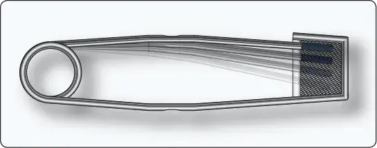 |
| Figure 8. Torch lighter |
Filler Rod
The use of the proper type of filler rod is very important for oxy-acetylene welding. This material adds not only reinforcement to the weld area, but also desired properties to the finished weld. By selecting the proper rod, tensile strength or ductility can be secured in a weld. Similarly, the proper rod can help retain the desired amount of corrosion resistance. In some cases, a suitable rod with a lower melting point helps to avoid cracks caused by expansion and contraction.
Welding rods may be classified as ferrous or nonferrous. Ferrous rods include carbon and alloy steel rods, as well as cast-iron rods. Nonferrous rods include brass, aluminum, magnesium, copper, silver, and their various alloys.
Welding rods are manufactured in standard 36 inch lengths and in diameters from 1⁄16-inch to 3⁄8-inch. The diameter of the rod to be used is governed by the thickness of the metals to be joined. If the rod is too small, it cannot conduct heat away from the puddle rapidly enough, and a burned hole results. A rod too large in diameter draws heat away and chills the puddle, resulting in poor penetration of the joined metal. All filler rods should be cleaned prior to use.
Equipment Setup
Setting up acetylene welding equipment in preparation for welding should be accomplished in a systematic and definite order to avoid costly damage to equipment and to avoid creating a hazard for personnel.
Gas Cylinders
All cylinders should be stored and transported in the upright position, especially acetylene cylinders, because they contain an absorbent material saturated with liquid acetone. If the cylinder were laid on its side, allowing the acetone to enter and contaminate the regulator, hose, and torch, fuel starvation and a resultant flashback in the system could result. If an acetylene cylinder must be placed on its side for a period of time, it must be stored in the upright position for at least twice as long before being used. Gas cylinders should be secured, usually with a chain, in a permanent location or in a suitable mobile cart. The cylinder’s protective steel cap should not be removed until the cylinder is put into service.
Regulators
Prior to installing the regulator on a gas cylinder, open the cylinder shutoff valve for an instant to blow out any foreign material that may be lodged in the outlet. Close the valve and wipe off the connection with a clean oil-free cloth. Connect the acetylene pressure regulator to the acetylene cylinder and tighten the left-hand nut. Connect the oxygen pressure regulator to the oxygen cylinder and tighten the right-hand nut. The connection fittings are brass and do not require a lot of torque to prevent them from leaking. At this time, check to ensure the adjusting screw on each pressure regulator is backed out by turning counterclockwise until it turns freely.
Hoses
Connect the red hose with the left-hand threads to the acetylene pressure regulator and the green hose with the right-hand threads to the oxygen pressure regulator. This is the location, between the regulator and hose, in which flashback arrestors should be installed. Again, because the fittings are brass and easily damaged, tighten only enough to prevent leakage.
Stand off to the side away from the face of the gauges. Now, very slowly open the oxygen cylinder valve and read the cylinder gauge to check the contents in the tank. The oxygen cylinder shutoff valve has a double seat valve and should be opened fully against its stop to seat the valve and prevent a leak. The acetylene cylinder shutoff valve should be slowly opened just enough to get the cylinder pressure reading on the regulator and then one-half turn more. This allows a quick shutoff, if needed.
Both hoses should be blown out before attaching to the torch. This is accomplished for each cylinder by turning the pressure adjusting screw in (clockwise) until the gas escapes, and then quickly backing the screw out (counterclockwise) to shut off the flow. This should be done in a well-ventilated open space, free from sparks, flames, or other sources of ignition.
Connecting Torch
Connect the red hose with the left-hand thread connector nut to the left-hand thread fitting on the torch. Connect the green hose with the right-hand thread connector nut to the right-hand thread fitting on the torch. Close the valves on the torch handle and check all connections for leaks as follows:
- Turn in the adjusting screw on the oxygen pressure regulator until the working pressure indicates 10 psi. Turn in the adjusting screw on the acetylene pressure regulator until the working pressure indicates 5 psi.
- Back out both adjusting screws on the regulators and verify that the working pressure remains steady. If it drops and pressure is lost, a leak is indicated between the regulator and the torch.
- A general tightening of all connections should fix the leak. Repeat a check of the system.
- If a leak is still indicated by a loss in working pressure, a mixture of soapy water on all the connections reveals the source of the leak. Never check for a leak with a flame because a serious explosion could occur.
Select the Tip Size
Welding and cutting tips are available in a variety of sizes for almost any job, and are identified by number. The higher the number is, the bigger the hole in the tip is allowing more heat to be directed onto the metal and allowing thicker metal to be welded or cut.
Welding tips have one hole and cutting tips have a number of holes. The cutting tip has one large hole in the center for the cutting oxygen and a number of smaller holes around it that supply the fuel gas and oxygen for the preheating flame. The selection of the tip size is very important, not only for the quality of the weld and/or the efficiency of the cutting process, but for the overall operation of the welding equipment and safety of the personnel using it.
Starvation occurs if torch tips are operated at less than the required volume of gas, leading to tip overheating and possible flashbacks. Incorrect tip size and obstructed tip orifices can also cause overheating and/or flashback conditions.
All fuel cylinders have a limited capacity to deliver gas to the tip. That capacity is further limited by the gas contents remaining in the cylinder and the temperature of the cylinder.
The following provides some recommended procedures to guard against overheating and flashbacks:
- Refer to the manufacturer’s recommendations for tip size based on the metal’s thickness.
- Use the recommended gas pressure settings for the tip size being used.
- Provide the correct volume of gas as recommended for each tip size.
- Do not use an excessively long hose, one with multiple splices, or one that may be too small in diameter and restrict the flow of gas.
For example, an acetylene cylinder that has a capacity of 330 cubic feet has a maximum withdrawal of 47 cubic feet per hour. This is determined by dividing 330 (cylinder capacity) by 7 (one-seventh of the cylinder capacity).
As a safety precaution, it is recommended that flashback arrestors be installed between the regulators and the gas supply hoses of all welding outfits. Figure 9 shows recommended tip sizes of different manufacturers, for welding various thickness of metal.
 |
| Figure 9. Chart of recommended tip sizes for welding various thicknesses of metal |
Adjusting the Regulator Working Pressure
The working pressure should be set according to the manufacturer’s recommendation for the tip size that is being used to weld or cut. This is a recommended method that works for most welding and cutting operations.
In a well ventilated area, open the acetylene valve on the torch and turn the adjusting screw on the acetylene pressure regulator clockwise until the desired pressure is set. Close the acetylene valve on the torch. Then, set the oxygen pressure in the same manner by opening the oxygen valve on the torch and turning the adjusting screw clockwise on the oxygen regulator until desired pressure is set. Then, close the oxygen valve on the torch handle. With the working pressures set, the welding or cutting operation can be initiated.
Lighting and Adjusting the Torch
With the proper working pressures set for the acetylene and oxygen, open the torch acetylene valve a quarter to a half turn. Direct the torch away from the body and ignite the acetylene gas with the flint striker. Open the acetylene valve until the black sooty smoke disappears from the flame. The pure acetylene flame is long, bushy, and has a yellowish color. Open the torch oxygen valve slowly and the flame shortens and turns to a bluish-white color that forms a bright inner luminous cone surrounded by an outer flame envelope. This is a neutral flame that should be set before either a carburizing or oxidizing flame mixture is set.
Different Flames
The three types of flame commonly used for welding are neutral, carburizing, and oxidizing. Each serves a specific purpose. [Figure 10]
 |
| Figure 10. Oxy-acetylene flames |
Neutral Flame
The neutral flame burns at approximately 5,850 °F at the tip of the inner luminous cone and is produced by a balanced mixture of acetylene and oxygen supplied by the torch. The neutral flame is used for most welding because it does not alter the composition of the base metal. When using this flame on steel, the molten metal puddle is quiet and clear, and the metal flows to give a thoroughly fused weld without burning or sparking.
Carburizing Flame
The carburizing flame burns at approximately 5,700 °F at the tip of the inner core. It is also referred to as a reducing flame because it tends to reduce the amount of oxygen in the iron oxides. The flame burns with a coarse rushing sound and has a bluish-white inner cone, a white center cone, and a light blue outer cone.
The flame is produced by burning more acetylene than oxygen, and can be recognized by the greenish feathery tip at the end of the cone. The longer the feather, the more acetylene is in the mix. For most welding operations, the length of the feather should be about twice the length of the inner cone.
The carburizing flame is best used for welding high-carbon steels, for hard facing, and for welding such nonferrous metals and alloys as aluminum, nickel alloys, and Monel.
Oxidizing Flame
The oxidizing flame burns at approximately 6,300 °F and is produced by burning an excess of oxygen. It takes about two parts of oxygen to one part acetylene to produce this flame. It can be identified by the shorter outer flame and the small, white, inner cone. To obtain this flame, start with a neutral flame and then open the oxygen valve until the inner cone is about one-tenth of its original length. The oxidizing flame makes a hissing sound, and the inner cone is somewhat pointed and purplish in color at the tip.
The oxidizing flame does have some specific uses. A slightly oxidizing flame is used for bronze welding (brazing) of steel and cast iron. A stronger oxidizing flame is used for fusion welding of brass and bronze. If an oxidizing flame is used on steel, it causes the molten metal to foam, give off sparks, and burn.
Soft or Harsh Flames
With each size of tip, a neutral, carburizing, or oxidizing flame can be obtained. It is also possible to obtain a soft or harsh flame by decreasing or increasing the working pressure of both gases (observing the maximum working pressure of 15 psi for acetylene gas).
For some work, it may be desirable to have a soft or low velocity flame without a reduction of thermal output. This can be achieved by reducing the working pressure using a larger tip and closing the torch valves until the neutral flame is quiet and steady. It is especially desirable to use a soft flame when welding aluminum to avoid blowing holes in the metal when the puddle is formed.
Handling of the Torch
It should be cautioned that improper adjustment or handling of the torch may cause the flame to backfire or, in rare cases, to flashback. A backfire is a momentary backward flow of gases at the torch tip that causes the flame to go out. A backfire may be caused by touching the tip against the work, overheating the tip, by operating the torch at other than recommended pressures, by a loose tip or head, or by dirt or slag in the end of the tip, and may cause molten metal to be splattered when the flame pops.
A flashback is dangerous because it is the burning of gases within the torch. It is usually caused by loose connections, improper pressures, or overheating of the torch. A shrill hissing or squealing noise accompanies a flashback, and unless the gases are turned off immediately, the flame may burn back through the hose and regulators causing great damage and personal injury. The cause of the flashback should always be determined and the problem corrected before relighting the torch. All gas welding outfits should have a flashback arrestor.
What is the maximum safe pressure setting for acetylene?
How do you distinguish between oxygen and acetylene hoses?
What is the difference between a backfire and a flashback?
Which flame type is used for most aircraft welding operations?
Why is it important to clean torch tips with the proper size cleaner?
RELATED POSTS