Several welding processes are used in aircraft manufacturing and repair. Each process uses a different method to generate heat and join metal, and each is best suited to specific materials, thicknesses, and repair situations.
| Process | Heat Source | Primary Aviation Use |
|---|---|---|
| Gas (Oxy-Acetylene) | Chemical Flame (6,300°F) | 4130 steel tubing; vintage aircraft repairs. |
| Stick (SMAW) | Consumable Electrode | Heavy structural steel; legacy airframes (e.g., Stinson). |
| MIG (GMAW) | Automated Wire Feed | High-volume manufacturing; not for critical repairs. |
| TIG (GTAW) | Tungsten Electrode | Preferred: Stainless, magnesium, and aluminum repair. |
| Spot / Seam | Material Resistance | Sheet metal parts and fuel tank manufacturing. |
| Plasma Arc (PAW) | Ionized Gas | Automated high-precision or miniature thin-gauge work. |
Gas Welding
Gas welding is accomplished by heating the ends or edges of metal parts to a molten state with a high temperature flame. The oxy-acetylene flame, with a temperature of approximately 6,300 °F, is produced with a torch burning acetylene and mixing it with pure oxygen. Hydrogen may be used in place of acetylene for aluminum welding, but the heat output is reduced to about 4,800 °F. Gas welding was the method most commonly used in production on aircraft materials less than 3⁄16 inch thick until the mid 1950s, when it was replaced by electric welding for economic (not engineering) reasons. Gas welding continues to be a very popular and proven method for repair operations.
Nearly all gas welding in aircraft fabrication is performed with oxy-acetylene welding equipment consisting of:
- Two cylinders, acetylene and oxygen.
- Acetylene and oxygen pressure regulators and cylinder pressure gauges.
- Two lengths of colored hose (red for acetylene and green for oxygen) with adapter connections for the regulators and torch.
- A welding torch with an internal mixing head, various-sized tips, and hose connections.
- Welding goggles fitted with appropriate colored lenses.
- A flint or spark lighter.
- Special wrench for acetylene tank valve if needed.
- An appropriately-rated fire extinguisher.
The equipment may be permanently installed in a shop, but most welding outfits are of the portable type. [Figure 1]
 |
| Figure 1. Portable oxy-acetylene welding outfit |
Electric Arc Welding
Electric arc welding is used extensively by the aircraft industry in both the manufacture and repair of aircraft. It can be used satisfactorily to join all weldable metals, provided that the proper processes and materials are used. The four types of electric arc welding are addressed in the following paragraphs.
Shielded Metal Arc Welding (SMAW)
Shielded metal arc welding (SMAW) is the most common type of welding and is usually referred to as “stick” welding. The equipment consists of a metal wire rod coated with a welding flux that is clamped in an electrode holder that is connected by a heavy electrical cable to a low-voltage, high-current power source using either alternating current (AC) or direct current (DC), depending on the type of welding being done. An arc is struck between the rod and the work and produces heat in excess of 10,000 °F, which melts both the material and the rod. The welding circuit consists of a welding machine, two leads, an electrode holder, an electrode, and the work to be welded. [Figure 2]
 |
| Figure 2. Typical arc welding circuit |
When the electrode is touched to the metal to be welded, the circuit is complete and the current flows. The electrode is then withdrawn from the metal approximately 1⁄4 inch to form an air gap between the metal and the electrode. If the correct gap is maintained, the current bridges the gap to form a sustained electric spark called the arc. This action melts the electrode and the coating of flux.
As the flux melts, it releases an inert gas that shields the molten puddle from oxygen in the air to prevent oxidation. The molten flux covers the weld and hardens to an airtight slag that protects the weld bead as it cools. Some aircraft manufacturers, such as Stinson, used this process for the welding of 4130 steel fuselage structures. This was followed by heat treatment in an oven to stress relieve and normalize the structure. Shown in Figure 3 is a typical arc welding machine with cables, ground clamp, and electrode holder.
 |
| Figure 3. Stick welder–Shielded Metal Arc Welder (SMAW) |
Gas Metal Arc Welding (GMAW)
Gas metal arc welding (GMAW) was formerly called gas inert gas (MIG) welding. It is an improvement over stick welding because an uncoated wire electrode is fed into and through the torch and an inert gas, such as argon, helium, or carbon dioxide, flows out around the wire to protect the puddle from oxygen. The power supply is connected to the torch and the work, and the arc produces the intense heat needed to melt the work and the electrode. [Figure 4]
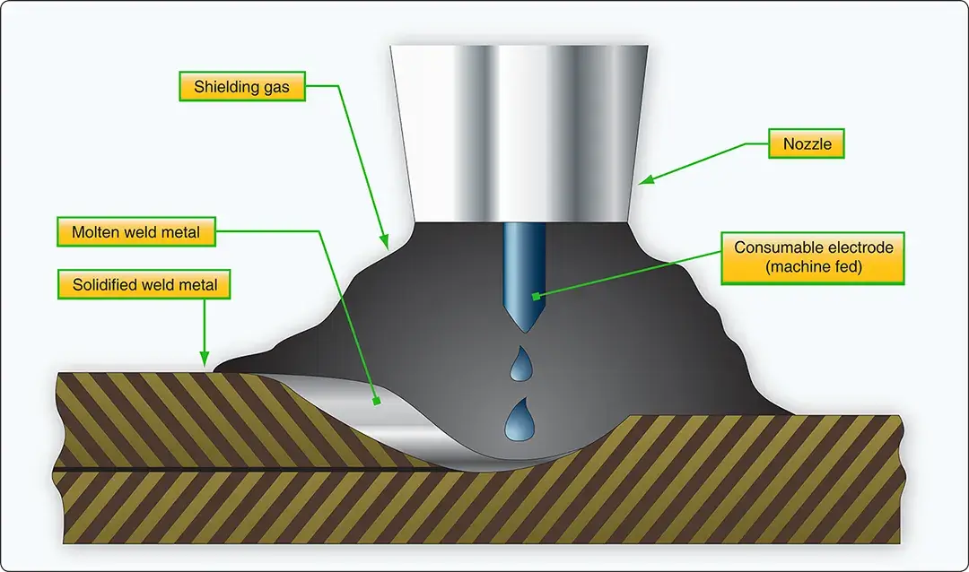 |
| Figure 4. Metal inert gas (MIG) welding process |
Low-voltage, high-current DC is typically used with GMAW welding. Figure 5 shows the equipment required for a typical MIG welding setup.
 |
| Figure 5. MIG welding equipment |
This method of welding can be used for large volume manufacturing and production work; it is not well suited to repair work because weld quality cannot be easily determined without destructive testing. Figure 6 depicts a typical power source used for MIG welding.
 |
| Figure 6. MIG welder–gas metal arc welder (GMAW) |
Gas Tungsten Arc Welding (GTAW)
Gas tungsten arc welding (GTAW) is a method of electric arc welding that fills most of the needs in aircraft maintenance and repair when proper procedures and materials are used. It is the preferred method to use on stainless steel, magnesium, and most forms of thick aluminum. It is more commonly known as Tungsten Inert Gas (TIG) welding and by the trade names of Heliarc or Heliweld. These names were derived from the inert helium gas that was originally used.
The first two methods of electric arc welding that were addressed used a consumable electrode that produced the filler for the weld. In TIG welding, the electrode is a tungsten rod that forms the path for the high amperage arc between it and the work to melt the metal at over 5,400 °F. The electrode is not consumed and used as filler so a filler rod is manually fed into the molten puddle in almost the same manner as when using an oxy-acetylene torch. A stream of inert gas, such as argon or helium, flows out around the electrode and envelopes the arc thereby preventing the formation of oxides in the molten puddle. [Figure 7]
 |
| Figure 7. Tungsten inert gas (TIG) welding process |
The versatility of a TIG welder is increased by the choice of the power supply being used. DC of either polarity or AC may be used. [Figure 8]
- Select DC straight polarity (electrode negative, work positive) when welding mild steel, stainless steel, and titanium.; or
- Select AC for welding aluminum and magnesium.
 |
| Figure 8. Typical setup for TIG welding |
Figure 9 is a typical power source for TIG welding along with a torch, foot-operated current control, regulator for inert gas, and assorted power cables.
 |
| Figure 9. TIG welder–gas tungsten arc welder (GTAW) |
Electric Resistance Welding
Electric resistance welding, either spot welding or seam welding, is typically used to join thin sheet metal components during the manufacturing process.
Spot Welding
Two copper electrodes are held in the jaws of the spot welding machine, and the material to be welded is clamped between them. Pressure is applied to hold the electrodes tightly together and electrical current flows through the electrodes and the material. The resistance of the material being welded is so much higher than that of the copper electrodes that enough heat is generated to melt the metal. The pressure on the electrodes forces the molten spots in the two pieces of metal to unite, and this pressure is held after the current stops flowing long enough for the metal to solidify. The amount of current, pressure, and dwell time are all carefully controlled and matched to the type of material and the thickness to produce the correct spot welds. [Figure 10]
 |
| Figure 10. Spot welding thin sheet metal |
Seam Welding
Rather than having to release the electrodes and move the material to form a series of spot welds, a seam-welding machine is used to manufacture of fuel tanks and other components where a continuous weld is needed. Two copper wheels replace the bar-shaped electrodes. The metal to be welded is moved between them, and electric pulses create spots of molten metal that overlap to form the continuous seam.
Plasma Arc Welding (PAW)
Plasma arc welding (PAW) was developed in 1964 as a method of bringing better control to the arc welding process. PAW provides an advanced level of control and accuracy using automated equipment to produce high quality welds in miniature and precision applications. Furthermore, PAW is equally suited to manual operation and can be performed by a person using skills similar to those for GTAW.
In the plasma welding torch, a nonconsumable tungsten electrode is located within a fine-bore copper nozzle. A pilot arc is initiated between the torch electrode and nozzle tip. This arc is then transferred to the metal being welded. [Figure 11]
 |
| Figure 11. The plasma welding process |
By forcing the plasma gas and arc through a constricted orifice, the torch delivers a high concentration of heat to a small area. The plasma process produces exceptionally high quality welds. [Figure 12]
 |
| Figure 12. Plasma arc |
Plasma gas is normally argon. The torch also uses a secondary gas, such as argon/helium or argon/nitrogen, that assists in shielding the molten weld puddle and minimizing oxidation of the weld.
Like GTAW, the PAW process can be used to weld most commercial metals, and it can be used for a wide variety of metal thicknesses. On thin material, from foil to 1⁄8-inch, the process is desirable because of the low heat input. The process provides relatively constant heat input because arc length variations are not very critical. On material thicknesses greater than 1⁄8-inch and using automated equipment, a keyhole technique is often used to produce full penetration single-path welds. In the keyhole technique, the plasma completely penetrates the workpiece. The molten weld metal flows to the rear of the keyhole and solidifies as the torch moves on. The high-quality welds produced are characterized by deep, narrow penetration and a small weld face.
When PAW is performed manually, the process requires a high degree of welding skills similar to that required for GTAW. However, the equipment is more complex and requires a high degree of knowledge to set up and use. The equipment required for PAW includes a welding machine, a special plasma arc control system, the plasma welding torch (water-cooled), the source of plasma and shielding gas, and filler material, when required. Because of the cost associated with this equipment, this process is very limited outside of manufacturing facilities.
Plasma Arc Cutting
When a plasma cutting torch is used, the gas is usually compressed air. The plasma cutting machine works by constricting an electrical arc in a nozzle and forcing the ionized gas through it. This heats the gas that melts the metal which is blown away by the air pressure. By increasing air pressure and intensifying the arc with higher voltages, the cutter is capable of blasting through thicker metals and blowing away the dross with minimal cleanup.
Plasma arc systems can cut all electrically conductive metals, including aluminum and stainless steel. These two metals cannot be cut by oxy-fuel cutting systems because they have an oxide layer that prevents oxidation from occurring. Plasma cutting works well on thin metals and can successfully cut brass and copper in excess of two inches thick.
Plasma cutting machines can rapidly and precisely cut through, gouge, or pierce any electrically conductive metal without preheating. The plasma cutter produces a precise kerf (cut) width and a small heat-affected zone (HAZ) that prevents warping and damage.
What is the preferred welding method for aircraft repair?
Why is MIG welding rarely used for aircraft structural repairs?
Can aluminum be cut with an oxy-acetylene torch?
What gas is typically used for shielding in TIG welding?
RELATED POSTS