Computer Graphics
From the early days of aviation, development of aircraft, aircraft engines, and other components relied heavily on aircraft drawings. For most of the 20th century, drawings were created on a drawing “board” with pen or pencil and paper. With the introduction and advancement of computers in the later decades of the 20th century, the way drawings are created changed dramatically. Computers were used not only to create drawings, but they were being used to show items in “virtual reality,” from any possible viewing angle. Further development of computer software programs allowed for assembling of separately created parts to check for proper fit and possible interferences. Additionally, with nearly instantaneous information sharing capability through computer networking and the Internet, it became much easier for designers to share their work with other designers and manufacturers virtually anytime, anywhere in the world. Using new computer-controlled manufacturing techniques, it became possible to design a part and have it precisely manufactured without ever having shown it on paper. New terms and acronyms became commonplace.
The more common of these terms are:
- Computer Graphics—drawing with the use of a computer
- Computer Aided Design (CAD)—where a computer is used in the design of a part or product
- Computer Aided Design Drafting (CADD)—where a computer is used in the design and drafting process
- Computer Aided Manufacturing (CAM)—where a computer is used in the manufacturing of a part or product
- Computer Aided Engineering (CAE)—where a computer is used in the engineering of a part or product
As computer hardware and software continue to evolve, a greater amount of CAE is completed in less time, at lower cost. In addition to product design, some of the other uses of CAE are product analysis, assembly, simulations, and maintenance information. [Figure 1]
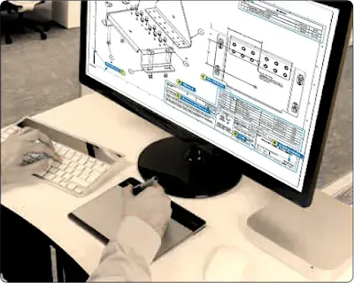 |
| Figure 1. Computer graphics work station |
CATIA, ProEngineer, Solid Works, and Unigraphics are some of the more popular CAD software packages used for aircraft design and manufacturing. Most airframe manufacturers use CATIA software to design their aircraft. The complete aircraft is designed and assembled in the software package before it is manufactured. Drawings of all parts of the aircraft are available and can be accessed using the computer software. Drawings are no longer limited to 1, 2, or 3 views. Drawings from every angle can easily be accessed by using the computer model of the part or product. Technicians can access drawings and aircraft manuals on laptops or even mobile devices when performing maintenance on the shop floor.
Purpose and Function of Aircraft Drawings
Drawings and prints are the link between the engineers who design an aircraft and the workers who build, maintain, and repair it. A print may be a copy of a working drawing for an aircraft part or group of parts, or for a design of a system or group of systems. They are made by placing a tracing of the drawing over a sheet of chemically-treated paper and exposing it to a strong light for a short period of time. When the exposed paper is developed, it turns blue where the light has penetrated the transparent tracing. The inked lines of the tracing, having blocked out the light, show as white lines on a blue background. With other types of sensitized paper, prints may have a white background with colored lines or a colored background with white lines.
Drawings created using computers may be viewed on the computer monitor or printed out in “hard copy” by use of an ink jet or laser printer. Larger drawings may be printed by use of a plotter or large format printer. Large printers can print drawings up to 42 inches high with widths up to 600 inches by use of continuous roll paper. [Figure 2]
 |
| Figure 2. Large format printer |
Care and Use of Drawings
Drawings should be handled carefully as they are both expensive and valuable. Open drawings slowly and carefully to prevent tearing of the paper. When the drawing is open, smooth out the fold lines instead of bending them backward.
To protect drawings from damage, never spread them on the floor or lay them on a surface covered with tools or other objects that may make holes in the paper. Hands should be free of oil, grease, or other unclean matter that can soil or smudge the print.
Never make notes or marks on a print, as they may confuse others and lead to incorrect work. Only authorized individuals are permitted to make notes or changes on prints, and they must sign and date any changes they make.
When finished with a drawing, fold and return it to its proper place. Prints are folded originally in an appropriate size for filing. Care should be taken so that the original folds are always used.
Types of Drawings
Drawings must give information such as size and shape of the object and all its parts, specifications for material to be used, how the material is to be finished, how the parts are to be assembled, and any other information essential to making and assembling the object. Drawings may be divided into three classes: detail, assembly, and installation.
Detail Drawing
A detail drawing is a description of a single part, describing by lines, notes, and symbols the specifications for size, shape, material, and methods of manufacture to be used in making the part. Detail drawings are usually rather simple. When single parts are small, several detail drawings may be shown on the same sheet or print. [Figure 3]
 |
| Figure 3. Detail drawing |
Assembly Drawing
An assembly drawing is a description of an object made up of two or more parts. [Figure 4] It describes the object’s size and shape. Its primary purpose is to show the relationship of the various parts. An assembly drawing is usually more complex than a detail drawing and is often accompanied by detail drawings of various parts.
 |
| Figure 4. Assembly drawing |
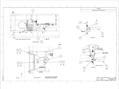
Installation Drawing
An installation drawing is one that includes all necessary information for a part or an assembly in the final installed position in the aircraft. It shows the dimensions necessary for the location of specific parts with relation to the other parts and reference dimensions that are helpful in later work in the shop. [Figure 5]
 |
| Figure 5. Installation drawing |
Sectional View Drawings
A section or sectional view is obtained by cutting away part of an object to show the shape and construction at the cutting plane. The part or parts cut away are shown by using section (crosshatching) lines. Types of sections are described in the following paragraphs.
Full Section
A full section view is used when the interior construction or hidden features of an object cannot be shown clearly by exterior views. For example, Figure 6 is a sectional view of a cable connector and shows the internal construction of the connector.
 |
| Figure 6. Sectional view of a cable connector |
Half Section
In a half section, the cutting plane extends only halfway across the object, leaving the other half of the object as an exterior view. Half sections are used with symmetrical objects to show both the interior and exterior. Figure 7 is a half sectional view of a Capstan servo.
 |
| Figure 7. Half section of a Capstan servo |
Revolved Section
A revolved section drawn directly on the exterior view shows the shape of the cross section of a part, such as the spoke of a wheel. An example of a revolved section is shown in Figure 8.
 |
| Figure 8. Revolved sections |
Removed Section
A removed section illustrates parts of an object. It is drawn like revolved sections, except it is placed at one side and often drawn to a larger scale than the view indicated to bring out pertinent details.
Figure 9 is an illustration of removed sections. Section A-A shows the cross-sectional shape of the object at cutting plane line A-A. Section B-B shows the cross-sectional shape at cutting plane line B-B. These sectional views are drawn to the same scale as the principal view.
 |
| Figure 9. Removed sections |
RELATED POSTS


