Applied Geometry
Geometry is the branch of mathematics that deals with lines, angles, figures, and certain assumed properties in space. Applied geometry, as used in drawings, makes use of these properties to accurately and correctly represent objects graphically. In the past, draftsmen utilized a variety of instruments with various scales, shapes, and curves to make their drawings. Today, computer software graphics programs show drawings at nearly any scale, shape, and curve imaginable, outdating the need for additional instruments. Several methods are used to illustrate objects graphically. The most common are orthographic projections, pictorial drawings, diagrams, and flowcharts.
Orthographic Projection Drawings
To show the exact size and shape of all the parts of complex objects, several views are necessary. This is the system used in orthographic projection.
In orthographic projection, there are six possible views of an object, because all objects have six sides—front, top, bottom, rear, right side, and left side. Figure 1A shows an object placed in a transparent box, hinged at the edges. The projections on the sides of the box are the views as seen looking straight at the object through each side. If the outlines of the object are drawn on each surface of the box, and the box is then opened [Figure 1B] to lay flat [Figure 1C], the result is a six-view orthographic projection.
 |
| Figure 1. Orthographic projection |
It is seldom necessary to show all six views to portray an object clearly; therefore, only those views necessary to illustrate the required characteristics of the object are drawn. One-, two-, and three-view drawings are the most common. Regardless of the number of views used, the arrangement is generally as shown in Figure 1, with the front view as principal view. If the right-side view is shown, it will be to the right of the front view. If the left-side view is shown, it will be to the left of the front view. The top and bottom views, if included, will be shown in their respective positions relative to the front view.
One-view drawings are commonly used for objects of uniform thickness, such as gaskets, shims, and plates. A dimensional note gives the thickness as shown in Figure 2. One-view drawings are also commonly used for cylindrical, spherical, or square parts if all the necessary dimensions can be properly shown in one view. When space is limited and two views must be shown, symmetrical objects are often represented by half views, as illustrated in Figure 3.
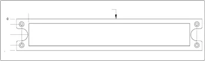 |
| Figure 2. One-view drawing |
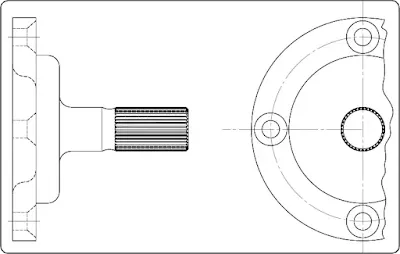 |
| Figure 3. Symmetrical object with exterior half view |
Aircraft drawings seldom show more than two principal or complete views of an object. Instead, there will be usually one complete view and one or more detail views or sectional views.
Detail View
A detail view shows only a part of the object, but in greater detail and to a larger scale than the principal view. The part that is shown in detail elsewhere on the drawing is usually encircled by a heavy line on the principal view. [Figure 4] The principal view shows the complete object, while the detail view is an enlarged drawing of a portion of the object.
 |
| Figure 4. Detail view |
Pictorial Drawings
A pictorial drawing is like a photograph. [Figure 5] It shows an object as it appears to the eye, but it is not satisfactory for showing complex forms and shapes. Pictorial drawings are useful in showing the general appearance of an object and are used extensively with orthographic projection drawings. Pictorial drawings are used in Aircraft Maintenance Manuals (AMM), Structural Repair Manuals (SRM), and Illustrated Parts Catalogues (IPC). Three types of pictorial drawings used frequently by aircraft engineers and technicians are: perspective, isometric, oblique, and exploded view.
 |
| Figure 5. Pictorial drawing |
Perspective Drawings
A perspective view shows an object as it appears to an observer. [Figure 6A] It most closely resembles the way an object would look in a photograph. Because of perspective, some of the lines of an object are not parallel and therefore the actual angles and dimensions are not accurate.
 |
| Figure 6. (A) Perspective, (B) isometric, and (C) oblique drawings |
Isometric Drawings
An isometric view uses a combination of the views of an orthographic projection and tilts the object forward so that portions of all three views can be seen in one view. [Figure 6B] This provides the observer with a three-dimensional view of the object. Unlike a perspective drawing where lines converge and dimensions are not true, lines in an isometric drawing are parallel and dimensioned as they are in an orthographic projection.Oblique Drawings
An oblique view is like an isometric view, except for one distinct difference. In an oblique drawing, two of the three drawing axes are always at right angles to each other.[Figure 6C]
Exploded View Drawings
An exploded view drawing is a pictorial drawing of two or more parts that fit together as an assembly. The view shows the individual parts and their relative position to the other parts before they are assembled. [Figure 7]
 |
| Figure 7. Exploded view drawing |
Exploded view drawings are often used in IPCs that are used to order parts. The exploded view drawing has numbers and the numbers correspond to a list of part numbers. Exploded views are also used in Maintenance Instruction Manuals (MIM) for the assembly and repair of aircraft components. These drawings are often accompanied by notes that explain the assembly process.
Diagrams
A diagram may be defined as a graphic representation of an assembly or system, indicating the various parts and expressing the methods or principles of operation. There are many types of diagrams; however, those that the aviation mechanic is concerned with during the performance of his or her job may be grouped into four classes or types: installation, schematic, block, and wiring diagrams.Installation Diagrams
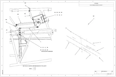
Figure 8 is an example of an installation diagram. This is a diagram of the installation of the flight guidance control components of an aircraft. It identifies each of the components in the systems and shows their location in the aircraft. Each number (1, 2, 3, and 4) on the detail shows the location of the individual flight guidance system components within the flight deck of the aircraft. Installation diagrams are used extensively in aircraft maintenance and repair manuals, and are invaluable in identifying and locating components and understanding the operation of various systems.
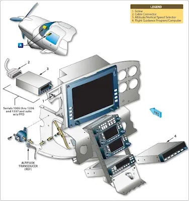 |
| Figure 8. Example of an installation diagram (flight guidance components) |
Schematic Diagrams
Schematic diagrams do not indicate the location of the individual components in the aircraft nor do they show the actual size and shape of the components, but rather locate components with respect to each other within the system. Schematics show the principle of operation of an aircraft system and are often used for troubleshooting and training purposes.
Figure 9 illustrates a schematic diagram of an aircraft air conditioning system. High speed bleed air from the engine is combined with cold air in the mixing chamber and distributed via a manifold to various parts of the aircraft.
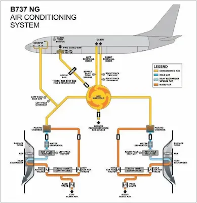 |
| Figure 9. Schematic diagram of an air conditioning system for a B737 NG |
Note that each line is coded for ease of reading and tracing the flow. Each component is identified by name, and its location within the system can be ascertained by noting the lines that lead into and out of the unit. Schematic diagrams and installation diagrams are used extensively in aircraft manuals.
Block Diagrams
Block diagrams are used to show a simplified relationship of a more complex system of components. [Figure 10] Individual components are drawn as a rectangle (block) with lines connecting it to other components (blocks) that it interfaces with during operation.
 |
| Figure 10. Block diagram |
Wiring Diagrams
Wiring diagrams show the electrical wiring and circuitry, coded for identification, of all the electrical appliances and devices used on aircraft. [Figure 11] These diagrams, even for relatively simple circuits, can be quite complicated. For technicians involved with electrical repairs and installations, a thorough knowledge of wiring diagrams and electrical schematics is essential.
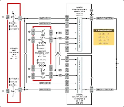 |
| Figure 11. Wiring diagram |
Flowcharts
Flowcharts are used to illustrate a sequence or flow of events. There are two types of flow charts most frequently used in the aviation industry: troubleshooting flowcharts and logic flowcharts.
Troubleshooting Flowchart
Troubleshooting flowcharts are frequently used for the detection of faulty components. They often consist of a series of yes or no questions. If the answer to a question is yes, one course of action is followed. If the answer is no, a different course of action is followed. In this simple manner, a logical solution to a problem may be achieved. Figure 12 shows a flow chart to determine the repair options for a composite structure.
 |
| Figure 12. Troubleshooting flowchart |
Logic Flowchart
Another type of flowchart, developed specifically for analysis of digitally-controlled components and systems, is the logic flowchart. [Figure 13] A logic flowchart uses standardized symbols to indicate specific types of logic gates and their relationship to other digital devices in a system. Since digital systems make use of binary mathematics consisting of 1s and 0s, voltage or no voltage, a light pulse or no light pulse, and so forth, logic flowcharts consist of individual components that take an input and provide an output that is either the same as the input or opposite. By analyzing the input or multiple inputs, it is possible to determine the digital output or outputs.
 |
| Figure 13. Logic flowchart |


