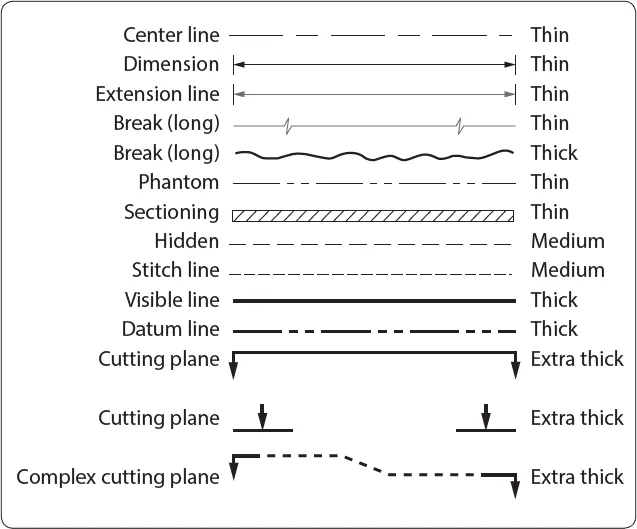
Lines and Their Meanings
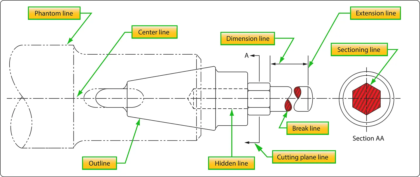
Every drawing is composed of lines. Lines mark the boundaries, edges, and intersection of surfaces. Lines are used to show dimensions and hidden surfaces and to indicate centers. Obviously, if the same kind of line is used to show these variations, a drawing becomes a meaningless collection of lines. For this reason, various kinds of standardized lines are used on aircraft drawings. [Figure 1] Examples of correct line uses are shown in Figure 2.
 |
| Figure 1. The meaning of lines |
 |
| Figure 2. Correct use of lines |
Most drawings use three widths, or intensities, of lines: thin, medium, or thick. These lines may vary somewhat on different drawings, but there is a noticeable difference between a thin and a thick line, with the width of the medium line somewhere between the two.
Centerlines
Centerlines are made up of alternate long and short dashes. They indicate the center of an object or part of an object. Where centerlines cross, the short dashes intersect symmetrically. In the case of very small circles, the centerlines may be shown unbroken.
Dimension Lines
A dimension line is a light solid line, broken at the midpoint for insertion of measurement indications, and having opposite pointing arrowheads at each end to show origin and termination of a measurement. They are generally parallel to the line that the dimension is given for, placed outside the outline of the object, and between views if more than one view is shown.
All dimensions and lettering are placed so that they read from left to right. The dimension of an angle is indicated by placing the degree of the angle in its arc. The dimensions of circular parts are always given in terms of the diameter of the circle and are usually marked with the letter D or the abbreviation DIA following the dimension. The dimension of an arc is given in terms of its radius and is marked with the letter R following the dimension. Parallel dimensions are placed so that the longest dimension is farthest from the outline and the shortest dimension is closest to the outline of the object. On a drawing showing several views, the dimensions are placed upon each view to show its details to the best advantage.
In dimensioning distances between holes in an object, dimensions are usually given from center to center rather than from outside to outside of the holes. When several holes of various sizes are shown, the desired diameters are given on a leader followed by notes indicating the machining operations for each hole. If a part is to have three holes of equal size, equally spaced, this information is explicitly stated. For precision work, sizes are given in decimals. Diameters and depths are given for counterbored holes. For countersunk holes, the angle of countersinking and the diameters are given. [Figure 3]
 |
| Figure 3. Dimensioning holes |
The dimensions given for tolerances signify the amount of clearance allowable between moving parts. A positive allowance is indicated for a part that is to slide or revolve upon another part. A negative allowance is one given for a force fit. Whenever possible, the tolerance and allowances for desired fits conform to those set up in the American Standard for Tolerances, Allowances, and Gauges for Metal Fits. The classes of fits specified in the standard may be indicated on assembly drawings.
Extension Lines
Extensions are used to extend the line showing the side or edge of a figure for placing a dimension to that side or edge. They are very narrow and have a short break where they extend from the object and extend a short distance past the arrow of the dimensioning line.
Sectioning Lines
Sectioning lines indicate the exposed surfaces of an object in a sectional view. They are generally thin full lines, but may vary with the kind of material shown in section.
Phantom Lines
Phantom lines indicate the alternate position of parts of the object or the relative position of a missing part. They are composed of one long and two short evenly spaced dashes.
Break Lines
Break lines indicate that a portion of the object is not shown on the drawing. Short breaks are made by solid, freehand lines. For long breaks, solid ruled lines with zigzags are used. Shafts, rods, tubes, and other such parts that have a portion of their length broken out have the ends of the break drawn as indicated in Figure 2.
Leader Lines
Leader lines are solid lines with one arrowhead. They indicate a part or portion that a note, number, or other reference applies.
Hidden Lines
Hidden lines indicate invisible edges or contours. Hidden lines consist of short dashes evenly spaced and are frequently referred to as dash lines.
Outline or Visible Lines
The outline or visible line is used for all lines on the drawing representing visible lines on the object. This is a medium-towide line that represents edges and surfaces that can be seen when the object is viewed directly.
Stitch Lines
Stitch lines are used to indicate the stitching or sewing lines on an article and consists of a series of very short dashes, approximately half the length of dash or hidden lines, evenly spaced. Long lines of stitching may be indicated by a series of stitch lines connected by phantom lines.
Cutting Plane and Viewing Plane Lines
Cutting plane lines indicate the plane where a sectional view of the object is taken. In Figure 2, plane line A indicates the plane that section AA is taken. Viewing plane lines indicate the plane from where a surface is viewed.
Drawing Symbols
The drawings for a component are composed largely of symbols and conventions representing its shape and material. Symbols are the shorthand of drawing. They graphically portray the characteristics of a component with a minimal amount of drawing.
Material Symbols
Section line symbols show the kind of material from which the part is to be constructed. The material may not be indicated symbolically if its exact specification is shown elsewhere on the drawing. In this case, the more easily drawn symbol for cast iron is used for the sectioning, and the material specification is listed in the bill of materials or indicated in a note. Figure 4 illustrates a few standard material symbols.
 |
| Figure 4. Standard material symbols |
Shape Symbols
Symbols can be used to excellent advantage when needed to show the shape of an object. Typical shape symbols used on aircraft drawings are shown in Figure 5. Shape symbols are usually shown on a drawing as a revolved or removed section.
 |
| Figure 5. Shape symbols |
Electrical Symbols
Electrical symbols represent various electrical devices rather than an actual drawing of the units. [Figure 6] Having learned what the various symbols indicate, it becomes relatively simple to look at an electrical diagram and determine what each unit is, what function it serves, and how it is connected in the system.
 |
| Figure 6. Electrical symbols |