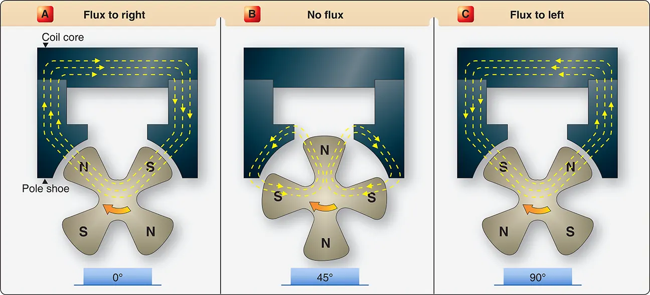
Figure 2 shows that as the magnet moves from the full register position 0°, flux flow decreases and reaches a zero value as it moves into the neutral position 45°. While the magnet moves through the neutral position, flux flow reverses and begins to increase as indicated by the curve below the horizontal line. At the 90° position, another position of maximum flux is reached. Thus, for one revolution 360° of the four pole magnet, there are four positions of maximum flux, four positions of zero flux, and four flux reversals.
This discussion of the magnetic circuit demonstrates how the coil core is affected by the rotating magnet. It is subjected to an increasing and decreasing magnetic field and a change in polarity each 90° of magnet travel.
When a coil of wire as part of the magneto’s primary electrical circuit is wound around the coil core, it is also affected by the varying magnetic field.
The primary electrical circuit consists of a set of breaker contact points, a condenser, and an insulated coil. [Figure 3] The coil is made up of a few turns of heavy copper wire, one end is grounded to the coil core and the other end to the ungrounded side of the breaker points. [Figure 3] The primary circuit is complete only when the ungrounded breaker point contacts the grounded breaker point. The third unit in the circuit, the condenser (capacitor), is wired in parallel with the breaker points. The condenser prevents arcing at the points when the circuit is opened and hastens the collapse of the magnetic field about the primary coil.
With the magnetic rotor in E-gap position and the primary coil holding the magnetic field of the magnetic circuit in the opposite polarity, a very high rate of flux change can be obtained by opening the primary breaker points. Opening the breaker points stops the flow of current in the primary circuit and allows the magnetic rotor to quickly reverse the field through the coil core. This sudden flux reversal produces a high rate of flux change in the core, that cuts across the secondary coil of the magneto (wound over and insulated from the primary coil), inducing the pulse of high-voltage electricity in the secondary needed to fire a spark plug. As the rotor continues to rotate to approximately full register position, the primary breaker points close again and the cycle is repeated to fire the next spark plug in firing order. The sequence of events can now be reviewed in greater detail to explain how the state of extreme magnetic stress occurs.
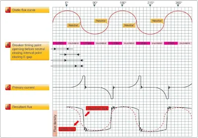
With the breaker points, cam, and condenser connected in the circuit as shown in Figure 4, the action that takes place as the magnetic rotor turns is depicted by the graph curve in Figure 5. At the top (A) of Figure 5, the original static flux curve of the magnets is shown. Shown below the static flux curve is the sequence of opening and closing the magneto breaker points. Note that opening and closing the breaker points is timed by the breaker cam. The points close when a maximum amount of flux is passing through the coil core and open at a position after neutral. Since there are four lobes on the cam, the breaker points close and open in the same relation to each of the four neutral positions of the rotor magnet. Also, the point opening and point closing intervals are approximately equal.
 |
| Figure 4. Components of a high-tension magneto circuit |
 |
| Figure 5. Magneto flux curves |
Starting at the maximum flux position marked 0° at the top of Figure 5, the sequence of events in the following paragraphs occurs.
As the magnet rotor is turned toward the neutral position, the amount of flux through the core starts to decrease. [Figure 5D] This change in flux linkages induces a current in the primary winding. [Figure 5C] This induced current creates a magnetic field of its own that opposes the change of flux linkages inducing the current. Without current flowing in the primary coil, the flux in the coil core decreases to zero as the magnet rotor turns to neutral and starts to increase in the opposite direction (dotted static flux curve in Figure 5D). But, the electromagnetic action of the primary current prevents the flux from changing and temporarily holds the field instead of allowing it to change (resultant flux line in Figure 5D).
As a result of the holding process, there is a very high stress in the magnetic circuit by the time the magnet rotor has reached the position where the breaker points are about to open. The breaker points, when opened, function with the condenser to interrupt the flow of current in the primary coil, causing an extremely rapid change in flux linkages. The high-voltage in the secondary winding discharges across the gap in the spark plug to ignite the fuel/air mixture in the engine cylinder. Each spark actually consists of one peak discharge, after which a series of small oscillations takes place.
They continue to occur until the voltage becomes too low to maintain the discharge. Current flows in the secondary winding during the time that it takes for the spark to completely discharge. The energy or stress in the magnetic circuit is completely dissipated by the time the contacts close for the production of the next spark. Breaker assemblies, used in high-tension magneto-ignition systems, automatically open and close the primary circuit at the proper time in relation to piston position in the cylinder to which an ignition spark is being furnished. The interruption of the primary current flow is accomplished through a pair of breaker contact points made of an alloy that resists pitting and burning.
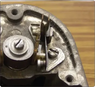
Most breaker points used in aircraft ignition systems are of the pivotless type in which one of the breaker points is movable and the other stationary. [Figure 6] The movable breaker point attached to the leaf spring is insulated from the magneto housing and is connected to the primary coil. [Figure 6] The stationary breaker point is grounded to the magneto housing to complete the primary circuit when the points are closed and can be adjusted so that the points can open at the proper time.
 |
| Figure 6. Pivotless type breaker assembly and cam |
Another part of the breaker assembly is the cam follower, which is spring-loaded against the cam by the metal leaf spring. The cam follower is a Micarta block or similar material that rides the cam and moves upward to force the movable breaker contact away from the stationary breaker contact each time a lobe of the cam passes beneath the follower. A felt oiler pad is located on the underside of the metal spring leaf to lubricate and prevent corrosion of the cam.
The breaker-actuating cam may be directly driven by the magneto rotor shaft or through a gear train from the rotor shaft. Most large radial engines use a compensated cam that is designed to operate with a specific engine and has one lobe for each cylinder to be fired by the magneto. The cam lobes are machine ground at unequal intervals to compensate for the elliptical path of the articulated connecting rods. This path causes the pistons top dead center position to vary from cylinder to cylinder with regard to crankshaft rotation. A compensated 14-lobe cam, together with a two-, four-, and eight-lobe uncompensated cam, is shown in Figure 7.
 |
| Figure 7. Typical breaker assemblies |
The unequal spacing of the compensated cam lobes, although it provides the same relative piston position for ignition to occur, causes a slight variation of the E-gap position of the rotating magnet and thus a slight variation in the high-voltage impulses generated by the magneto. Since the spacing between each lobe is tailored to a particular cylinder of a particular engine, compensated cams are marked to show the series of the engine, the location of the master rods, the lobe used for magneto timing, the direction of cam rotation, and the E-gap specification in degrees past neutral of magnet rotation. In addition to these markings, a step is cut across the face of the cam, that, when aligned with scribed marks on the magneto housing, places the rotating magnet in the E-gap position for the timing cylinder. Since the breaker points should begin to open when the rotating magnet moves into the E-gap position, alignment of the step on the cam with marks in the housing provides a quick and easy method of establishing the exact E-gap position to check and adjust the breaker points.
The Secondary Electrical Circuit
The secondary circuit contains the secondary windings of the coil, distributor rotor, distributor cap, ignition lead, and spark plug. The secondary coil is made up of a winding containing approximately 13,000 turns of fine, insulated wire; one end of which is electrically grounded to the primary coil or to the coil core and the other end connected to the distributor rotor. The primary and secondary coils are encased in a non-conducting material. The whole assembly is then fastened to the pole shoes with screws and clamps.
When the primary circuit is closed, the current flow through the primary coil produces magnetic lines of force that cut across the secondary windings, inducing an electromotive force. When the primary circuit current flow is stopped, the magnetic field surrounding the primary windings collapses, causing the secondary windings to be cut by the lines of force. The strength of the voltage induced in the secondary windings, when all other factors are constant, is determined by the number of turns of wire. Since most high-tension magnetos have many thousands of turns of wire in the secondary coil windings, a very high-voltage, often as high as 20,000 volts, is generated in the secondary circuit. The high-voltage induced in the secondary coil is directed to the distributor, which consists of two parts: revolving and stationary. The revolving part is called a distributor rotor and the stationary part is called a distributor block. The rotating part, which may take the shape of a disk, drum, or finger, is made of a non-conducting material with an embedded conductor. The stationary part consists of a block also made of non-conducting material that contains terminals and terminal receptacles into which the ignition lead wiring that connects the distributor to the spark plug is attached. This high-voltage is used to jump the air gap of electrodes of the spark plug in the cylinder to ignite the fuel/air mixture.
As the magnet moves into the E-gap position for the No. 1 cylinder and the breaker points just separate or open, the distributor rotor aligns itself with the No. 1 electrode in the distributor block. The secondary voltage induced as the breaker points open enters the rotor where it arcs a small air gap to the No. 1 electrode in the block.
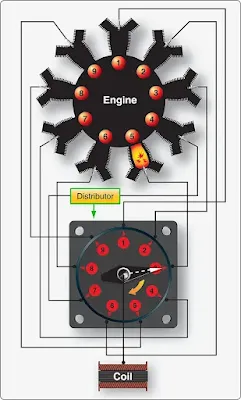
Since the distributor rotates at one-half crankshaft speed on all four-stroke cycle engines, the distributor block has as many electrodes as there are engine cylinders, or as many electrodes as cylinders served by the magneto. The electrodes are located circumferentially around the distributor block so that, as the rotor turns, a circuit is completed to a different cylinder and spark plug each time there is alignment between the rotor finger and an electrode in the distributor block. The electrodes of the distributor block are numbered consecutively in the direction of distributor rotor travel. [Figure 8]
 |
| Figure 8. Relation between distributor terminal numbers and cylinder numbers |
The distributor numbers represent the magneto sparking order rather than the engine cylinder numbers. The distributor electrode marked “1” is connected to the spark plug in the No. 1 cylinder; distributor electrode marked “2” to the second cylinder to be fired; distributor electrode marked “3” to the third cylinder to be fired, and so forth.
In Figure 8, the distributor rotor finger is aligned with the distributor electrode marked “3,” which fires the No. 5 cylinder of a nine-cylinder radial engine. Since the firing order of a nine-cylinder radial engine is 1-3-5-7-9-2-4-6-8, the third electrode in the magneto sparking order serves the No. 5 cylinder.
Magneto and Distributor Venting
Since magneto and distributor assemblies are subjected to sudden changes in temperature, the problems of condensation and moisture are considered in the design of these units. Moisture in any form is a good conductor of electricity. If absorbed by the nonconducting material in the magneto, such as distributor blocks, distributor fingers, and coil cases, it can create a stray electrical conducting path. The high-voltage current that normally arcs across the air gaps of the distributor can flash across a wet insulating surface to ground, or the high-voltage current can be misdirected to some spark plug other than the one that should be fired. This condition is called flashover and usually results in cylinder misfiring. This can cause a serious engine condition called pre-ignition, which can damage the engine. For this reason, coils, condensers, distributors, and distributor rotors are waxed so that moisture on such units stand in separate beads and do not form a complete circuit for flashover.
Flashover can lead to carbon tracking, which appears as a fine pencil-like line on the unit across which flashover occurs. The carbon trail results from the electric spark burning dirt particles that contain hydrocarbon materials. The water in the hydrocarbon material is evaporated during flashover, leaving carbon to form a conducting path for current. When moisture is no longer present, the spark continues to follow the carbon track to the ground. This prevents the spark from getting to the spark plug, so the cylinder does not fire.
Magnetos cannot be hermetically sealed to prevent moisture from entering a unit, because the magneto is subject to pressure and temperature changes in altitude. Thus, adequate drains and proper ventilation reduce the tendency of flashover and carbon tracking. Good magneto circulation also ensures that corrosive gases produced by normal arcing across the distributor air gap, such as ozone, are carried away. In some installations, pressurization of the internal components of the magnetos and other various parts of the ignition system is essential to maintain a higher absolute pressure inside the magneto and to eliminate flashover due to high altitude flight. This type of magneto is used with turbocharged engines that operate at higher altitudes. Flashover becomes more likely at high altitudes because of the lower air pressure, which makes it easier for the electricity to jump air gaps. By pressurizing the interior of the magneto, the normal air pressure is maintained and the electricity or the spark is held within the proper areas of the magneto even though the ambient pressure is very low.
Even in a pressurized magneto, the air is allowed to flow through and out of the magneto housing. By providing more air and allowing small amounts of air to bleed out for ventilation, the magneto remains pressurized. Regardless of the method of venting employed, the vent bleeds or valves must be kept free of obstructions. Further, the air circulating through the components of the ignition system must be free of oil since even minute amounts of oil on ignition parts result in flashover and carbon tracking.
Ignition Harness
The ignition lead directs the electrical energy from the magneto to the spark plug. The ignition harness contains an insulated wire for each cylinder that the magneto serves in the engine. [Figure 9] One end of each wire is connected to the magneto distributor block and the other end is connected to the proper spark plug. The ignition harness leads serve a dual purpose. It provides the conductor path for the high-tension voltage to the spark plug. It also serves as a shield for stray magnetic fields that surround the wires as they momentarily carry high-voltage current. By conducting these magnetic lines of force to the ground, the ignition harness cuts down electrical interference with the aircraft radio and other electrically sensitive equipment.
 |
| Figure 9. A high-tension ignition harness |
A magneto is a high frequency radiation emanating (radio wave) device during its operation. The wave oscillations produced in the magneto are uncontrolled and cover a wide range of frequencies and must be shielded. If the magneto and ignition leads were not shielded, they would form antennas and pick up the random frequencies from the ignition system. The lead shielding is a medal mesh braid that surrounds the entire length of the lead. The lead shielding prevents the radiation of the energy into the surrounding area.
Capacitance is the ability to store an electrostatic charge between two conducting plates separated by a dielectric. Lead insulation is called a dielectric, meaning it can store electrical energy as an electrostatic charge. An example of electrostatic energy storage in a dielectric is the static electricity stored in a plastic hair comb. When shielding is placed around the ignition lead, capacitance increases by bringing the two plates closer together. Electrically, the ignition lead acts as a capacitor and has the ability to absorb and store electrical energy. The magneto must produce enough energy to charge the capacitance caused by the ignition lead and have enough energy left over to fire the plug.
Ignition lead capacitance increases the electrical energy required to provide a spark across the plug gap. More magneto primary current is needed to fire the plug with the shielded lead. This capacitance energy is discharged as fire across the plug gap after each firing of the plug. By reversing the polarity during servicing by rotating the plugs to new locations, the plug wear is equalized across the electrodes. The very center of the ignition lead is the high-voltage carrier surrounded by a silicone insulator material that is surrounded by a metal mesh, or shielding, covered with a thin silicone rubber coating that prevents damage by engine heat, vibration, or weather.
A sectional view of the typical ignition lead is shown in Figure 10. Ignition leads must be routed and clamped correctly to avoid hot spots on the exhaust and vibration points as the leads are routed from the magneto to the individual cylinders. Ignition leads are normally of the all-weather type and are hard connected at the magneto distributor and affixed to the spark plug by threads. The shielded ignition lead spark plug terminal is available in all-weather 3/4 inch diameter and 5/8 inch diameter barrel ignition lead nut. [Figure 11] The 5/8 – 24 plug takes a 3/4 wrench on the lead nut and the 3/4 – 20 plug takes a 7/8 wrench on the lead nut. The 3/4 inch all-weather design utilizes a terminal seal that results in greater terminal well insulation. This is recommended because the lead end of the spark plug is completely sealed from moisture.
 |
| Figure 10. Ignition lead |
 |
| Figure 11. Ignition lead spark plug end |
An older radial engine type of ignition harness is a manifold formed to fit around the crankcase of the engine with flexible extensions terminating at each spark plug. A typical high-tension ignition harness is shown in Figure 12. Many older single-row radial engine aircraft ignition systems employ a dual-magneto system, in which the right magneto supplies the electric spark for the front plugs in each cylinder, and the left magneto fires the rear plugs.
 |
| Figure 12. Accessory-mounted nine cylinder engine ignition harness |
Ignition Switches
All units in an aircraft ignition system are controlled by an ignition switch. The type of switch used varies with the number of engines on the aircraft and the type of magnetos used. All switches, however, turn the system off and on in much the same manner. The ignition switch is different in at least one respect from all other types of switches: when the ignition switch is in the off position, a circuit is completed through the switch to ground. In other electrical switches, the off position normally breaks or opens the circuit.
The ignition switch has one terminal connected to the primary electrical circuit between the coil and the breaker contact points. The other terminal of the switch is connected to the aircraft ground structure. As shown in Figure 13, two ways to complete the primary circuit are:
- Through the closed breaker points to ground and
- Through the closed ignition switch to ground
Figure 13 shows that the primary current is not interrupted when the breaker contacts open since there is still a path to ground through the closed, or off, ignition switch. Since primary current is not stopped when the contact points open, there can be no sudden collapse of the primary coil flux field and no high-voltage induced in the secondary coil to fire the spark plug.
As the magnet rotates past the electrical gap (E-gap) position, a gradual breakdown of the primary flux field occurs. But that breakdown occurs so slowly that the induced voltage is too low to fire the spark plug. Thus, when the ignition switch is in the off position with the switch closed, the contact points are as completely short-circuited as if they were removed from the circuit, and the magneto is inoperative.
When the ignition switch is placed in the on position switch open, the interruption of primary current and the rapid collapse of the primary coil flux field is once again controlled or triggered by the opening of the breaker contact points. [Figure 14] When the ignition switch is in the on position, the switch has absolutely no effect on the primary circuit.
 |
| Figure 14. Typical ignition switch in on position |
The ignition/starter switch, or magneto switch, controls the magnetos on or off and can also connect the starter solenoid for turning the starter. When a starting vibrator, a box that emits pulsating direct current (DC), is used on the engine, the ignition/starter switch is used to control the vibrator and retard points. This system is explained in detail later in this chapter. Some ignition starter switches have a push to prime feature during the starting cycle. This system allows additional fuel to spray into the intake port of the cylinder during the starting cycle.
Single and Dual High-Tension System Magnetos
High-tension system magnetos used on aircraft engines are either single or dual type magnetos. The single magneto design incorporates the distributor in the housing with the magneto breaker assembly, rotating magnet, and coil. [Figure 15] The dual magneto incorporates two magnetos contained in a single housing. One rotating magnet and a cam are common to two sets of breaker points and coils. Two separate distributor units are mounted in the magneto. [Figure 16]
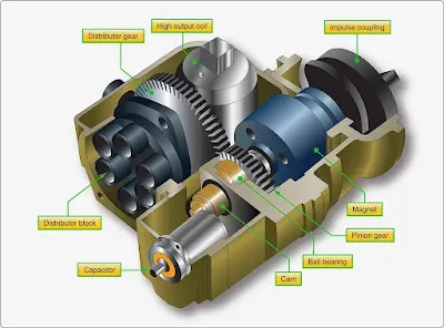 |
| Figure 15. Magneto cutaway |
 |
| Figure 16. A dual magneto with two distributors |
Magneto Mounting Systems
Flange-mounted magnetos are attached to the engine by a flange around the driven end of the rotating shaft of the magneto. [Figure 17] Elongated slots in the mounting flange permit adjustment through a limited range to aid in timing the magneto to the engine. Some magnetos mount by the flange and use clamps on each side to secure the magneto to the engine. This design also allows for timing adjustments. Base mounted magnetos are only used on very old or antique aircraft engines.
 |
| Figure 17. Magneto mounting flange |
Low-Tension Magneto System
High-tension ignition systems have undergone many refinements and improvements in design. This includes new electronic systems that control more than just providing ignition to the cylinders. High-tension voltage presents certain problems with carrying the high-voltage from the magneto internally and externally to the spark plugs. In early years, it was difficult to provide insulators that could contain the high-voltage, especially at high altitudes when the air pressures were reduced. Another requirement of high-tension systems was that all weather and radio-equipped aircraft have ignition wires enclosed in shielding to prevent radio noise due to high-voltages. Many aircraft were turbosupercharged and operated at increased high altitudes. The low pressure at these altitudes would allow the high-voltage to leak out even more. To meet these problems, low-tension ignition systems were developed.
Electronically, the low-tension system is different from the high-tension system. In the low-tension system, low-voltage is generated in the magneto and flows to the primary winding of a transformer coil located near the spark plug. There, the voltage is increased to high by transformer action and conducted to the spark plug by very short high-tension leads. [Figure 18]
 |
| Figure 18. Simplified low-tension ignition system schematic |
The low-tension system virtually eliminates flashover in both the distributor and the harness because the air gaps within the distributor have been eliminated by the use of a brush-type distributor, and high-voltage is present only in short leads between the transformer and spark plug.
Although a certain amount of electrical leakage is characteristic of all ignition systems, it is more pronounced on radio-shielded installations because the metal conduit is at ground potential and close to the ignition wires throughout their entire length. In low-tension systems, however, this leakage is reduced considerably because the current throughout most of the system is transmitted at a low-voltage potential. Although the leads between the transformer coils and the spark plugs of a low-tension ignition system are short, they are high-tension high-voltage conductor, and are subject to the same failures that occur in high-tension systems. Low-tension ignition systems have limited use in modern aircraft because of the excellent materials and shielding available to construct high-tension ignition leads and the added cost of a coil for each spark plug with the low-tension system.
RELATED POSTS