Other than this difference, the systems use similar types of components. Because the dry sump system contains all the components of the wet sump system, the dry sump system is explained as an example system.
Combination Splash and Pressure Lubrication
The lubricating oil is distributed to the various moving parts of a typical internal combustion engine by one of the three following methods: pressure, splash, or a combination of pressure and splash.
The pressure lubrication system is the principal method of lubricating aircraft engines. Splash lubrication may be used in addition to pressure lubrication on aircraft engines, but it is never used by itself; aircraft-engine lubrication systems are always either the pressure type or the combination pressure and splash type, usually the latter.
The advantages of pressure lubrication are:
- Positive introduction of oil to the bearings.
- Cooling effect caused by the large quantities of oil that can be pumped, or circulated, through a bearing.
- Satisfactory lubrication in various attitudes of flight.
Lubrication System Requirements
The lubrication system of the engine must be designed and constructed so that it functions properly within all flight attitudes and atmospheric conditions that the aircraft is expected to operate. In wet sump engines, this requirement must be met when only half of the maximum lubricant supply is in the engine. The lubrication system of the engine must be designed and constructed to allow installing a means of cooling the lubricant. The crankcase must also be vented to the atmosphere to preclude leakage of oil from excessive pressure.
Dry Sump Oil Systems
Many reciprocating and turbine aircraft engines have pressure dry sump lubrication systems. The oil supply in this type of system is carried in a tank. A pressure pump circulates the oil through the engine. Scavenger pumps then return it to the tank as quickly as it accumulates in the engine sumps. The need for a separate supply tank is apparent when considering the complications that would result if large quantities of oil were carried in the engine crankcase. On multiengine aircraft, each engine is supplied with oil from its own complete and independent system.
Although the arrangement of the oil systems in different aircraft varies widely and the units of which they are composed differ in construction details, the functions of all such systems are the same. A study of one system clarifies the general operation and maintenance requirements of other systems.
The principal units in a typical reciprocating engine dry sump oil system include an oil supply tank, an engine-driven pressure oil pump, a scavenge pump, an oil cooler with an oil cooler control valve, oil tank vent, necessary tubing, and pressure and temperature indicators. [Figure 1]
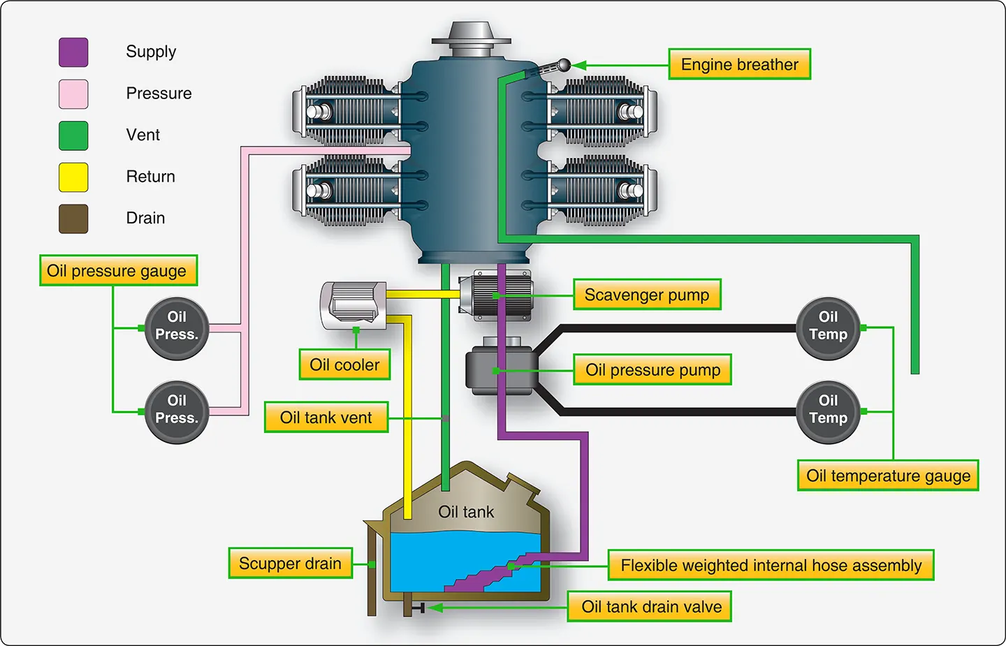 |
| Figure 1. Oil system schematic |
Oil Tanks
Oil tanks are generally associated with a dry sump lubrication system, while a wet sump system uses the crankcase of the engine to store the oil. Oil tanks are usually constructed of aluminum alloy and must withstand any vibration, inertia, and fluid loads expected in operation.
Each oil tank used with a reciprocating engine must have expansion space of not less than the greater of 10 percent of the tank capacity or 0.5 gallons. Each filler cap of an oil tank that is used with an engine must provide an oil-tight seal. The oil tank usually is placed close to the engine and high enough above the oil pump inlet to ensure gravity feed.
Oil tank capacity varies with the different types of aircraft, but it is usually sufficient to ensure an adequate supply of oil for the total fuel supply. The tank filler neck is positioned to provide sufficient room for oil expansion and for foam to collect.
The filler cap or cover is marked with the word OIL. A drain in the filler cap well disposes of any overflow caused by the filling operation. Oil tank vent lines are provided to ensure proper tank ventilation in all attitudes of flight. These lines are usually connected to the engine crankcase to prevent the loss of oil through the vents. This indirectly vents the tanks to the atmosphere through the crankcase breather.
Early large radial engines had many gallons of oil in their tank. To help with engine warm up, some oil tanks had a built-in hopper or temperature accelerating well. [Figure 2] This well extended from the oil return fitting on top of the oil tank to the outlet fitting in the sump in the bottom of the tank. In some systems, the hopper tank is open to the main oil supply at the lower end. Other systems have flapper-type valves that separate the main oil supply from the oil in the hopper.
 |
| Figure 2. Oil tank with hopper |
The opening at the bottom of the hopper in one type and the flapper valve-controlled openings in the other allow oil from the main tank to enter the hopper and replace the oil consumed by the engine. Whenever the hopper tank includes the flapper controlled openings, the valves are operated by differential oil pressure. By separating the circulating oil from the surrounding oil in the tank, less oil is circulated. This hastens the warming of the oil when the engine was started. Very few of these types of tanks are still in use and most are associated with radial engine installations.
Generally, the return line in the top of the tank is positioned to discharge the returned oil against the wall of the tank in a swirling motion. This method considerably reduces foaming that occurs when oil mixes with air. Baffles in the bottom of the oil tank break up this swirling action to prevent air from being drawn into the inlet line of the oil pressure pump. Foaming oil increases in volume and reduces its ability to provide proper lubrication. In the case of oil-controlled propellers, the main outlet from the tank may be in the form of a standpipe so that there is always a reserve supply of oil for propeller feathering in case of engine failure. An oil tank sump, attached to the under surface of the tank, acts as a trap for moisture and sediment. [Figure 1] The water and sludge can be drained by manually opening the drain valve in the bottom of the sump.
Most aircraft oil systems are equipped with the dipstick-type quantity gauge, often called a bayonet gauge. Some larger aircraft systems also have an oil quantity indicating system that shows the quantity of oil during flight. One type system consists essentially of an arm and float mechanism that rides the level of the oil and actuates an electric transmitter on top of the tank. The transmitter is connected to a cockpit gauge that indicates the quantity of oil.
Oil Pump
Oil entering the engine is pressurized, filtered, and regulated by units within the engine. They are discussed along with the external oil system to provide a concept of the complete oil system.
As oil enters the engine, it is pressurized by a gear-type pump. [Figure 3] This pump is a positive displacement pump that consists of two meshed gears that revolve inside the housing. The clearance between the teeth and housing is small. The pump inlet is located on the left and the discharge port is connected to the engine’s system pressure line. One gear is attached to a splined drive shaft that extends from the pump housing to an accessory drive shaft on the engine. Seals are used to prevent leakage around the drive shaft. As the lower gear is rotated counterclockwise, the driven idler gear turns clockwise.
 |
| Figure 3. Engine oil pump and associated units |
As oil enters the gear chamber, it is picked up by the gear teeth, trapped between them and the sides of the gear chamber, is carried around the outside of the gears, and discharged from the pressure port into the oil screen passage. The pressurized oil flows to the oil filter, where any solid particles suspended in the oil are separated from it, preventing possible damage to moving parts of the engine.
Oil under pressure then opens the oil filter check valve mounted in the top of the filter. This valve is used mostly with dry sump radial engines and is closed by a light spring loading of 1 to 3 pounds per square inch (psi) when the engine is not operating to prevent gravity-fed oil from entering the engine and settling in the lower cylinders or sump area of the engine. If oil were allowed to gradually seep by the rings of the piston and fill the combustion chamber, it could cause a liquid lock. This could happen if the valves on the cylinder were both closed and the engine was cranked for start. Damage could occur to the engine.
The oil filter bypass valve, located between the pressure side of the oil pump and the oil filter, permits unfiltered oil to bypass the filter and enter the engine if the oil filter is clogged or during cold weather if congealed oil is blocking the filter during engine start. The spring loading on the bypass valve allows the valve to open before the oil pressure collapses the filter; in the case of cold, congealed oil, it provides a low-resistance path around the filter. Dirty oil in an engine is better than no lubrication.
Oil Filters
The oil filter used on an aircraft engine is usually one of four types: screen, Cuno, canister, or spin-on. A screen-type filter with its double-walled construction provides a large filtering area in a compact unit. [Figure 3] As oil passes through the fine-mesh screen, dirt, sediment, and other foreign matter are removed and settle to the bottom of the housing. At regular intervals, the cover is removed and the screen and housing cleaned with a solvent. Oil screen filters are used mostly as suction filters on the inlet of the oil pump.
The Cuno oil filter has a cartridge made of disks and spacers. A cleaner blade fits between each pair of disks. The cleaner blades are stationary, but the disks rotate when the shaft is turned. Oil from the pump enters the cartridge well that surrounds the cartridge and passes through the spaces between the closely spaced disks of the cartridge, then through the hollow center, and on to the engine. Any foreign particles in the oil are deposited on the outer surface of the cartridge. When the cartridge is rotated, the cleaner blades comb the foreign matter from the disks. The cartridge of the manually operated Cuno filter is turned by an external handle. Automatic Cuno filters have a hydraulic motor built into the filter head. This motor, operated by engine oil pressure, rotates the cartridge whenever the engine is running. There is a manual turning nut on the automatic Cuno filter for rotating the cartridge manually during inspections. This filter is not often used on modern aircraft.
A canister housing filter has a replaceable filter element that is replaced with rest of the components other than seals and gaskets being reused. [Figure 4] The filter element is designed with a corrugated, strong steel center tube supporting each convoluted pleat of the filter media, resulting in a higher collapse pressure rating. The filter provides excellent filtration, because the oil flows through many layers of locked-in-fibers.
 |
| Figure 4. Housing filter element type oil filter |
Full flow spin-on filters are the most widely used oil filters for reciprocating engines. [Figure 5]
 |
| Figure 5. Full flow spin-on filter |
Full flow means that all the oil is normally passed through the filter. In a full flow system, the filter is positioned between the oil pump and the engine bearings, which filters the oil of any contaminants before they pass through the engine bearing surfaces. The filter also contains an antidrain back valve and a pressure relief valve, all sealed in a disposable housing. The relief valve is used in case the filter becomes clogged. It would open to allow the oil to bypass, preventing the engine components from oil starvation. A cutaway of the micronic filter element shows the resin-impregnated cellulosic full-pleat media that is used to trap harmful particles, keeping them from entering the engine. [Figure 6]
 |
| Figure 6. Cutaway view of a filter |
Oil Pressure Regulating Valve
An oil pressure regulating valve limits oil pressure to a predetermined value, depending on the installation. [Figure 3]
 |
| Figure 7. Oil pressure adjustment screw |
This valve is sometimes referred to as a relief valve, but its real function is to regulate the oil pressure at a preset pressure level. The oil pressure must be sufficiently high to ensure adequate lubrication of the engine and its accessories at high speeds and powers. This pressure helps ensure that the oil film between the crankshaft journal and bearing is maintained. However, the pressure must not be too high, as leakage and damage to the oil system may result. The oil pressure is generally adjusted by loosening the locknut and turning the adjusting screw. [Figure 7] On most aircraft engines, turning the screw clockwise increases the tension of the spring that holds the relief valve on its seat and increases the oil pressure; turning the adjusting screw counterclockwise decreases the spring tension and lowers the pressure. Some engines use washers under the spring that are either removed or added to adjust the regulating valve and pressure. The oil pressure should be adjusted only after the engine’s oil is at operating temperature and the correct viscosity is verified. The exact procedure for adjusting the oil pressure and the factors that vary an oil pressure setting are included in applicable manufacturer’s instructions.
Oil Pressure Gauge
Usually, the oil pressure gauge indicates the pressure that oil enters the engine from the pump. This gauge warns of possible engine failure caused by an exhausted oil supply, failure of the oil pump, burned-out bearings, ruptured oil lines, or other causes that may be indicated by a loss of oil pressure.
One type of oil pressure gauge uses a Bourdon-tube mechanism that measures the difference between oil pressure and cabin, or atmospheric, pressure. This gauge is constructed similarly to other Bourdon-type gauges, except that it has a small restriction built into the instrument case, or into the nipple connection leading to the Bourdon tube. This restriction prevents the surging action of the oil pump from damaging the gauge or causing the pointer to oscillate too violently with each pressure pulsation. The oil pressure gauge has a scale ranging from 0–200 psi, or from 0–300 psi. Operation range markings are placed on the cover glass, or the face of the gauge, to indicate the safe range of oil pressure for a given installation.
A dual-type oil pressure gauge is available for use on multiengine aircraft. The dual indicator contains two Bourdon tubes, housed in a standard instrument case; one tube being used for each engine. The connections extend from the back of the case to each engine. There is one common movement assembly, but the moving parts function independently. In some installations, the line leading from the engine to the pressure gauge is filled with light oil. Since the viscosity of this oil does not vary much with changes in temperature, the gauge responds better to changes in oil pressure. In time, engine oil mixes with some of the light oil in the line to the transmitter; during cold weather, the thicker mixture causes sluggish instrument readings. To correct this condition, the gauge line must be disconnected, drained, and refilled with light oil.
The current trend is toward electrical transmitters and indicators for oil and fuel pressure-indicating systems in all aircraft. In this type of indicating system, the oil pressure being measured is applied to the inlet port of the electrical transmitter where it is conducted to a diaphragm assembly by a capillary tube. The motion produced by the diaphragm’s expansion and contraction is amplified through a lever and gear arrangement. The gear varies the electrical value of the indicating circuit, which in turn, is reflected on the indicator in the cockpit. This type of indicating system replaces long fluid-filled tubing lines with an almost weightless piece of wire.
Oil Temperature Indicator
In dry-sump lubricating systems, the oil temperature bulb may be anywhere in the oil inlet line between the supply tank and the engine. Oil systems for wet-sump engines have the temperature bulb located where it senses oil temperature after the oil passes through the oil cooler. In either system, the bulb is located so that it measures the temperature of the oil before it enters the engine’s hot sections. An oil temperature gauge in the cockpit is connected to the oil temperature bulb by electrical leads. The oil temperature is indicated on the gauge. Any malfunction of the oil cooling system appears as an abnormal reading.
Oil Cooler
The cooler, either cylindrical or elliptical shaped, consists of a core enclosed in a double-walled shell. The core is built of copper or aluminum tubes with the tube ends formed to a hexagonal shape and joined together in the honeycomb effect. [Figure 8] The ends of the copper tubes of the core are soldered, whereas aluminum tubes are brazed or mechanically joined. The tubes touch only at the ends so that a space exists between them along most of their lengths. This allows oil to flow through the spaces between the tubes while the cooling air passes through the tubes.
 |
| Figure 8. Oil cooler |
The space between the inner and outer shells is known as the annular or bypass jacket. Two paths are open to the flow of oil through a cooler. From the inlet, it can flow halfway around the bypass jacket, enter the core from the bottom, and then pass through the spaces between the tubes and out to the oil tank. This is the path the oil follows when it is hot enough to require cooling. As the oil flows through the core, it is guided by baffles that force the oil to travel back and forth several times before it reaches the core outlet. The oil can also pass from the inlet completely around the bypass jacket to the outlet without passing through the core. Oil follows this bypass route when the oil is cold or when the core is blocked with thick, congealed oil.
Oil Cooler Flow Control Valve
As discussed previously, the viscosity of the oil varies with its temperature. Since the viscosity affects its lubricating properties, the temperature at which the oil enters an engine must be held within close limits. Generally, the oil leaving an engine must be cooled before it is recirculated. Obviously, the amount of cooling must be controlled if the oil is to return to the engine at the correct temperature. The oil cooler flow control valve determines which of the two possible paths the oil takes through the oil cooler. [Figure 9]
 |
| Figure 9. Control valve with surge protection |
There are two openings in a flow control valve that fit over the corresponding outlets at the top of the cooler. When the oil is cold, a bellows within the flow control contracts and lifts a valve from its seat. Under this condition, oil entering the cooler has a choice of two outlets and two paths. Following the path of least resistance, the oil flows around the jacket and out past the thermostatic valve to the tank. This allows the oil to warm up quickly and, at the same time, heats the oil in the core. As the oil warms up and reaches its operating temperature, the bellows of the thermostat expand and closes the outlet from the bypass jacket. The oil cooler flow control valve, located on the oil cooler, must now flow oil through the core of the oil cooler. No matter which path it takes through the cooler, the oil always flows over the bellows of the thermostatic valve. As the name implies, this unit regulates the temperature by either cooling the oil or passing it on to the tank without cooling, depending on the temperature at which it leaves the engine.
Surge Protection Valves
When oil in the system is congealed, the scavenger pump may build up a very high pressure in the oil return line. To prevent this high pressure from bursting the oil cooler or blowing off the hose connections, some aircraft have surge protection valves in the engine lubrication systems. One type of surge valve is incorporated in the oil cooler flow control valve; another type is a separate unit in the oil return line. [Figure 9]
The surge protection valve incorporated in a flow control valve is the more common type. Although this flow control valve differs from the one just described, it is essentially the same except for the surge protection feature. The high-pressure operation condition is shown in Figure 9, in which the high oil pressure at the control valve inlet has forced the surge valve (C) upward. Note how this movement has opened the surge valve and, at the same time, seated the poppet valve (E). The closed poppet valve prevents oil from entering the cooler proper; therefore, the scavenge oil passes directly to the tank through outlet (A) without passing through either the cooler bypass jacket or the core. When the pressure drops to a safe value, the spring forces the surge and poppet valves downward, closing the surge valve (C) and opening the poppet valve (E). Oil then passes from the control valve inlet (D), through the open poppet valve, and into the bypass jacket (F). The thermostatic valve, according to oil temperature, determines oil flow either through the bypass jacket to port (H) or through the core to port (G). The check valve (B) opens to allow the oil to reach the tank return line.
Airflow Controls
By regulating the airflow through the cooler, the temperature of the oil can be controlled to fit various operating conditions. For example, the oil reaches operating temperature more quickly if the airflow is cut off during engine warm-up. There are two methods in general use: shutters installed on the rear of the oil cooler, and a flap on the air-exit duct. In some cases, the oil cooler air-exit flap is opened manually and closed by a linkage attached to a cockpit lever. More often, the flap is opened and closed by an electric motor.
One of the most widely used automatic oil temperature control devices is the floating control thermostat that provides manual and automatic control of the oil inlet temperatures. With this type of control, the oil cooler air-exit door is opened and closed automatically by an electrically operated actuator. Automatic operation of the actuator is determined by electrical impulses received from a controlling thermostat inserted in the oil pipe leading from the oil cooler to the oil supply tank. The actuator may be operated manually by an oil cooler air-exit door control switch. Placing this switch in the “open” or “closed” position produces a corresponding movement of the cooler door. Placing the switch in the “auto” position puts the actuator under the automatic control of the floating control thermostat. [Figure 10] The thermostat shown in Figure 10 is adjusted to maintain a normal oil temperature so that it does not vary more than approximately 5° to 8 °C, depending on the installation.
 |
| Figure 10. Floating control thermostat |
During operation, the temperature of the engine oil flowing over the bimetal element causes it to wind or unwind slightly. [Figure 10B] This movement rotates the shaft (A) and the grounded center contact arm (C). As the grounded contact arm is rotated, it is moved toward either the open or closed floating contact arm (G). The two floating contact arms are oscillated by the cam (F), which is continuously rotated by an electric motor (D) through a gear train (E). When the grounded center contact arm is positioned by the bimetal element so that it touches one of the floating contact arms, an electric circuit to the oil cooler exit-flap actuator motor is completed, causing the actuator to operate and position the oil cooler air-exit flap. Newer systems use electronic control systems, but the function or the overall operation is basically the same regarding control of the oil temperature through control of the air flow through the cooler.
In some lubrication systems, dual oil coolers are used. If the typical oil system previously described is adapted to two oil coolers, the system is modified to include a flow divider, two identical coolers and flow regulators, dual air-exit doors, a two-door actuating mechanism, and a Y-fitting. [Figure 11]
 |
| Figure 11. Dual oil cooler system |
Oil is returned from the engine through a single tube to the flow divider (E), where the return oil flow is divided equally into two tubes (C), one for each cooler. The coolers and regulators have the same construction and operations as the cooler and flow regulator just described. Oil from the coolers is routed through two tubes (D) to a Y-fitting, where the floating control thermostat (A) samples oil temperature and positions the two oil cooler air-exit doors through the use of a two-door actuating mechanism. From the Y-fitting, the lubricating oil is returned to the tank where it completes its circuit.
Dry Sump Lubrication System Operation
The following lubrication system is typical of those on small, single-engine aircraft. The oil system and components are those used to lubricate a 225 horsepower (hp) six-cylinder, horizontally opposed, air-cooled engine. In a typical dry sump pressure-lubrication system, a mechanical pump supplies oil under pressure to the bearings throughout the engine. [Figure 1] The oil flows into the inlet or suction side of the oil pump through a suction screen and a line connected to the external tank at a point higher than the bottom of the oil sump. This prevents sediment that falls into the sump from being drawn into the pump. The tank outlet is higher than the pump inlet, so gravity can assist the flow into the pump. The engine-driven, positive-displacement, gear-type pump forces the oil into the full flow filter. [Figure 3] The oil either passes through the filter under normal conditions or, if the filter were to become clogged, the filter bypass valve would open as mentioned earlier. In the bypass position, the oil would not be filtered. As seen in Figure 3, the regulating (relief) valve senses when system pressure is reached and opens enough to bypass oil to the inlet side of the oil pump. Then, the oil flows into a manifold that distributes the oil through drilled passages to the crankshaft bearings and other bearings throughout the engine. Oil flows from the main bearings through holes drilled in the crankshaft to the lower connecting rod bearings. [Figure 12]
 |
| Figure 12. Oil circulation through the engine |
Oil reaches a hollow camshaft (in an inline or opposed engine), or a cam plate or cam drum (in a radial engine), through a connection with the end bearing or the main oil manifold; it then flows out to the various camshaft, cam drum, or cam plate bearings and the cams.
The engine cylinder surfaces receive oil sprayed from the crankshaft and also from the crankpin bearings. Since oil seeps slowly through the small crankpin clearances before it is sprayed on the cylinder walls, considerable time is required for enough oil to reach the cylinder walls, especially on a cold day when the oil flow is more sluggish. This is one of the chief reasons for using modern multiviscosity oils that flow well at low temperatures.
When the circulating oil has performed its function of lubricating and cooling the moving parts of the engine, it drains into the sumps in the lowest parts of the engine. Oil collected in these sumps is picked up by gear or gerotor-type scavenger pumps as quickly as it accumulates. These pumps have a greater capacity than the pressure pump. This is needed because the volume of the oil has generally increased due to foaming (mixing with air). On dry sump engines, this oil leaves the engine, passes through the oil cooler, and returns to the supply tank.
A thermostat attached to the oil cooler controls oil temperature by allowing part of the oil to flow through the cooler and part to flow directly into the oil supply tank. This arrangement allows hot engine oil with a temperature still below 65 °C (150 °F) to mix with the cold uncirculated oil in the tank. This raises the complete engine oil supply to operating temperature in a shorter period of time.
Wet-Sump Lubrication System Operation
A simple form of a wet-sump system is shown in Figure 13. The system consists of a sump or pan in which the oil supply is contained. The oil supply is limited by the sump (oil pan) capacity. The level (quantity) of oil is indicated or measured by a vertical rod that protrudes into the oil from an elevated hole on top of the crankcase. In the bottom of the sump (oil pan) is a screen strainer having a suitable mesh, or series of openings, to strain undesirable particles from the oil and yet pass sufficient quantity to the inlet or (suction) side of the oil pressure pump.
 |
| Figure 13. Basic wet-sump oil system |
Figure 14 shows a typical oil sump that has the intake tube running through it. This preheats the fuel-air mixture before it enters the cylinders.
 |
| Figure 14. Wet-sump system’s sump with intake tube running through it |
The rotation of the pump, which is driven by the engine, causes the oil to pass around the outside of the gears. [Figure 3] This develops a pressure in the crankshaft oiling system (drilled passage holes). The variation in the speed of the pump from idling to full-throttle operating range of the engine and the fluctuation of oil viscosity because of temperature changes are compensated by the tension on the relief valve spring. The pump is designed to create a greater pressure than required to compensate for wear of the bearings or thinning out of oil. The parts oiled by pressure throw a lubricating spray into the cylinder and piston assemblies. After lubricating the various units it sprays, the oil drains back into the sump and the cycle is repeated. The system is not readily adaptable to inverted flying since the entire oil supply floods the engine.