Large aircraft rely extensively on hydraulic systems to transmit power efficiently and reliably to critical aircraft components. Hydraulics are used in transport-category aircraft because they can produce very high forces with precise control while keeping system weight and component size to a minimum. This makes hydraulic power ideal for operating heavy loads such as flight control surfaces, landing gear, and braking systems.
In modern commercial aircraft, hydraulic systems typically operate at high pressure levels, commonly around 3,000 psi (207 bar). High-pressure operation improves system efficiency and reduces overall aircraft weight. To ensure safety and reliability, large aircraft hydraulic systems are designed with multiple independent systems, allowing continued operation even in the event of a pump failure, fluid leak, or loss of engine power.
Aircraft hydraulic systems supply power to many essential functions, including primary and secondary flight controls, landing gear extension and retraction, wheel brakes, nose wheel steering, thrust reversers, and high-lift devices such as flaps and slats. Because many of these systems are safety-critical, additional features such as standby systems, power transfer units, isolation valves, and emergency power sources are incorporated to maintain hydraulic capability during abnormal or emergency conditions.
Hydraulic fluid is stored in pressurized reservoirs and delivered to the system by engine-driven pumps, electric motor-driven pumps, or air turbine-driven pumps, depending on aircraft design and operating conditions. Heat exchangers, filters, pressure relief valves, and system sensors are installed to regulate fluid temperature, prevent contamination, protect against over-pressurization, and monitor system performance. Figure 1 provides an overview of hydraulic components in large aircraft.
 |
| Figure 1. Large aircraft hydraulic systems |
The following sections describe the hydraulic system architecture and operation of large transport aircraft, using the Boeing 737 Next Generation and Boeing 777 as representative examples to demonstrate common design features, redundancy concepts, and system protection methods used in modern aircraft hydraulic systems.
Boeing 737 Next Generation Hydraulic System
The Boeing 737 Next Generation has three 3,000 psi hydraulic systems: system A, system B, and standby. The standby system is used if system A and/or B pressure is lost. The hydraulic systems power the following aircraft systems:
- Flight controls
- Leading edge flaps and slats
- Trailing edge flaps
- Landing gear
- Wheel brakes
- Nose wheel steering
- Thrust reversers
- Autopilots
Reservoirs
The system A, B, and standby reservoirs are located in the wheel well area. The reservoirs are pressurized by bleed air through a pressurization module. The standby reservoir is connected to the system B reservoir for pressurization and servicing. The positive pressure in the reservoir ensures a positive flow of fluid to the pumps. The reservoirs have a standpipe that prevents the loss of all hydraulic fluid if a leak develops in the engine-driven pump or its related lines. The engine-driven pump draws fluid through a standpipe in the reservoir and the AC motor pump draws fluid from the bottom of the reservoir. [Figure 2]
 |
| Figure 2. Hydraulic reservoirs on a Boeing 737 |
Pumps
Refer to Figure 3 for the following description. Both A and B hydraulic systems have an engine-driven pump (EDP) and an ACMP. The system A engine-driven pump is installed on the number 1 engine and the system B engine-driven pump is installed on the number 2 engine. The AC pumps are controlled by a switch on the flight deck.
 |
| Figure 3. Boeing 737 hydraulic system (simplified) |
The hydraulic case drain fluid that lubricates and cools the pumps return to the reservoir through a heat exchanger. [Figure 4] The heat exchanger for the A system is installed in the main fuel tank No. 1, and the heat exchanger for the B system is installed in the main fuel tank No. 2. Minimum fuel for ground operation of electric motor-driven pumps is 1,675 pounds in the related main tank. Pressure switches, located in the EDP and ACMP pump output lines, send signals to illuminate the related LOW PRESSURE light if pump output pressure is low. The related system pressure transmitter sends the combined pressure of the EDP and ACMP to the related hydraulic system pressure indicator.
 |
| Figure 4. Boeing 737 hydraulic case drain fluid heat exchanger installed in the fuel tank |
Filter Units
Filter modules are installed in the pressure, case drain, and return lines to clean the hydraulic fluid. Filters have a differential pressure indicator that pops out when the filter is dirty and needs to be replaced.
Power Transfer Unit (PTU)
The purpose of the PTU is to supply the additional volume of hydraulic fluid needed to operate the autoslats and leading edge flaps and slats at the normal rate when system B EDP malfunctions. The PTU unit consists of a hydraulic motor and hydraulic pump that are connected through a shaft. The PTU uses system A pressure to drive a hydraulic motor. The hydraulic motor of the PTU unit is connected through a shaft with a hydraulic pump that can draw fluid from the system B reservoir. The PTU can only transfer power and cannot transfer fluid. The PTU operates automatically when all of the following conditions are met:
- System B EDP pressure drops below limits.
- Aircraft airborne.
- Flaps are less than 15° but not up.
Landing Gear Transfer Unit
The purpose of the landing gear transfer unit is to supply the volume of hydraulic fluid needed to raise the landing gear at the normal rate when system A EDP is lost. The system B EDP supplies the volume of hydraulic fluid needed to operate the landing gear transfer unit when all of the following conditions are met:
- Aircraft airborne.
- 1 engine rpm drops below a limit value.
- Landing gear lever is up.
- Either or both main landing gear not up and locked.
Standby Hydraulic System
The standby hydraulic system is provided as a backup if system A and/or B pressure is lost. The standby system can be activated manually or automatically and uses a single electric ACMP to power:
- Thrust reversers
- Rudder
- Leading edge flaps and slats (extend only)
- Standby yaw damper
Indications
A master caution light illuminates if an overheat or low pressure is detected in the hydraulic system. An overheat light on the flight deck illuminates if an overheat is detected in either system A or B and a low-pressure light illuminates if low pressure is detected in system A or system B.
Boeing 777 Hydraulic System
The Boeing 777 is equipped with three hydraulic systems. The left, center, and right systems deliver hydraulic fluid at a rated pressure of 3,000 psi (207 bar) to operate flight controls, flap systems, actuators, landing gear, and brakes. Primary hydraulic power for the left and right systems is provided by two EDPs and supplemented by two on-demand ACMPs. Primary hydraulic power for the center system is provided by two electric motor pumps (ACMP) and supplemented by two on-demand air turbine-driven pumps (ADP). The center system provides hydraulic power for the engine thrust reversers, primary flight controls, landing gear, and flaps/slats. Under emergency conditions, hydraulic power is generated by the ram air turbine (RAT), which is deployed automatically and drives a variable displacement inline pump. The RAT pump provides flow to the center system flight controls. [Figure 5]
 |
| Figure 5. A Boeing 777 hydraulic system |
Left and Right System Description
The left and right hydraulic systems are functionally the same. The left hydraulic system supplies pressurized hydraulic fluid to operate the left thrust reverser and the flight control systems. The right hydraulic system supplies pressurized hydraulic fluid to operate the right thrust reverser, flight control systems, and the normal brake system. [Figure 6]
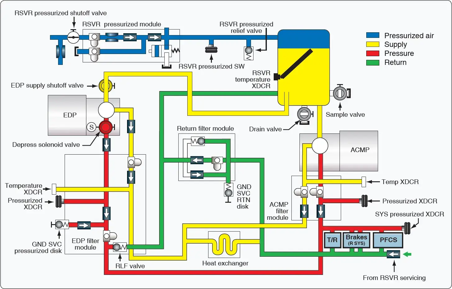 |
| Figure 6. Right hydraulic system of a Boeing 777. A left system is similar |
Reservoir
The hydraulic system reservoirs of the left and right system contain the hydraulic fluid supply for the hydraulic pumps. The reservoir is pressurized by bleed air through a reservoir pressurization module. The EDP draws fluid through a standpipe. The ACMP draws fluid from the bottom of the reservoir. If the fluid level in the reservoir gets below the standpipe, the EDP cannot draw any fluid any longer, and the ACMP is the only source of hydraulic power. The reservoir can be serviced through a center servicing point in the fuselage of the aircraft. The reservoir has a sample valve for contamination testing purposes, a temperature transmitter for temperature indication on the flight deck, a pressure transducer for reservoir pressure, and a drain valve for reservoir draining.
Pumps
The EDPs are the primary pumps for the left and right hydraulic systems. The EDPs get reservoir fluid through the EDP supply shutoff valves. The EDPs operate whenever the engines operate. A solenoid valve in each EDP controls the pressurization and depressurization of the pump. The pumps are variable displacement inline piston pumps consisting of a first stage impeller pump and a second stage piston pump. The impeller pump delivers fluid under pressure to the piston pump. The ACMPs are the demand pumps for the left and right hydraulic systems. The ACMPs normally operate only when there is high hydraulic system demand.
Filter Module
Pressure and case drain filter modules clean the pressure flows and the case drain flows of the hydraulic pumps. A return filter module cleans the return flow of hydraulic fluid from the user systems. The module can be bypassed if the filter clogs, and a visible indicator pops to indicate a clogged filter. The heat exchanger, which is installed in the wing fuel tanks, cools the hydraulic fluid from ACMP and EDP case drain lines before the fluid goes back to the reservoir.
Indication
The hydraulic system sensors send pressure, temperature, and quantity signals to the flight deck. A reservoir quantity transmitter and temperature transducer are installed on each of the reservoirs, and a hydraulic reservoir pressure switch is located on the pneumatic line between the reservoir pressurization module and the reservoir. The ACMP and EDP filter modules each have a pressure transducer to measure pump output pressure. A temperature transducer is installed in the case drain line of each filter module and measures pump case drain fluid temperature. A system pressure transducer measures hydraulic system pressure. A pressure relief valve on the EDP filter module protects the system against over pressurization. [Figure 6]
Center Hydraulic System
The center hydraulic system supplies pressurized hydraulic fluid to operate these systems [Figure 7]
- Nose landing gear actuation
- Nose landing gear steering
- Alternate brakes
- Main landing gear actuation
- Main landing gear steering
- Trailing edge flaps
- Leading edge slats
- Flight controls
 |
| Figure 7. Center hydraulic system |
Reservoir
The hydraulic system reservoir of the center system contains the hydraulic fluid supply for the hydraulic pumps. The reservoir is pressurized by bleed air through a reservoir pressurization module. The reservoir supplies fluid to the ADPs, the RAT, and one of the ACMPs through a standpipe. The other ACMP gets fluid from the bottom of the reservoir. The reservoir also supplies hydraulic fluid to the landing gear alternate extension system.
The ACMPs are the primary pumps in the center hydraulic system and are normally turned on. The ADPs are the demand pumps in the center system. They normally operate only when the center system needs more hydraulic flow capacity. The RAT system supplies an emergency source of hydraulic power to the center hydraulic system flight controls. A reservoir quantity transmitter and temperature transducer are installed on the reservoir. A hydraulic reservoir pressure switch is installed on the pneumatic line between the reservoir and the reservoir pressurization module.
Filter
Filter modules clean the pressure and case drain output of the hydraulic pumps. A return filter module cleans the return flow of hydraulic fluid from the user systems. The module can be bypassed. The heat exchanger cools the hydraulic fluid from the ACMP case drains before the fluid goes back to the reservoir. ADP case drain fluid does not go through the heat exchangers.
The ACMP and ADP filter modules each have a pressure transducer to measure pump output pressure. A temperature transducer in each filter module measures the pump case drain temperature. A system pressure transducer measures hydraulic system pressure.
Pressure relief valves in each ADP filter module prevent system overpressurization. A pressure relief valve near ACMP C1 supplies overpressure protection for the center hydraulic isolation system (CHIS).
Center Hydraulic Isolation System (CHIS)
The CHIS supplies engine burst protection and a reserve brakes and steering function. CHIS operation is fully automatic. Relays control the electric motors in the reserve and nose gear isolation valves. When the CHIS system is operational, it prevents hydraulic operation of the leading edge slats.
ACMP C1 gets hydraulic fluid from the bottom of the center system reservoir. All other hydraulic pumps in the center system get fluid through a standpipe in the reservoir. This gives ACMP C1 a 1.2 gallon (4.5 liter) reserve supply of hydraulic fluid.
The reserve and nose gear isolation valves are normally open. Both valves close if the quantity in the center system reservoir is low (less than 0.40) and the airspeed is more than 60 knots for more than one second. When CHIS is active, this divides the center hydraulic system into different parts. The NLG actuation and steering and the leading edge slat hydraulic lines are isolated from center system pressure. The output of ACMP C1 goes only to the alternate brake system.
The output of the other center hydraulic system pumps goes to the trailing edge flaps, the MLG actuation and steering, and the flight controls. If there is a leak in the NLG actuation and steering or LE slat lines, there is no further loss of hydraulic fluid. The alternate brakes, the trailing edge flaps, the MLG actuation and steering, and the PFCS continue to operate normally.
If there is a leak in the trailing edge flaps, the MLG actuation and steering, or the flight control lines, the reservoir loses fluid down to the standpipe level (0.00 indication). This causes a loss of these systems but the alternate brake system continues to get hydraulic power from ACMP C1. If there is a leak in the lines between ACMP C1 and the alternate brake system, all center hydraulic system fluid is lost.
Nose Gear Isolation Valve
The nose gear isolation valve opens for any of these conditions:
- Airspeed is less than 60 knots.
- Pump pressures for ACMP C2, ADP C1, ADP C2, and the RAT is less than 1,200 psi for 30 seconds.
- Left and right engine rpm is above idle, left and right EDP pressure is more than 2,400 psi, and the NLG is not up, the NLG doors are not closed, or the landing gear lever is not up for 30 seconds.
The first condition permits the flight crew to operate the NLG steering when airspeed is less than 60 knots (decreased rudder control authority during taxi). The second condition permits operation of the NLG actuation and steering if the hydraulic leak is in the part of the center hydraulic system isolated by the reserve isolation valve. The third condition permits operation of the NLG actuation and steering if there has not been an engine burst and the other hydraulic systems are pressurized. The nose gear isolation valve opens when pressure is necessary at the NLG. If the NLG is not fully retracted or the NLG doors are not closed, the nose gear isolation valve opens to let the NLG complete the retraction. When the landing gear lever is moved to the down position, the nose gear isolation valve opens to let the NLG extend with center system pressure.
Central Hydraulic System Reset
Both valves open again automatically when the center system quantity is more than 0.70 and airspeed is less than 60 knots for 5 seconds. Both valves also reset when the center system quantity is more than 0.70 and both engines and both engine-driven pumps operate normally for 30 seconds. [Figure 8]
 |
| Figure 8. Center hydraulic isolation system |