Hydraulic seals are essential components in aircraft hydraulic systems because they prevent fluid leakage, keep contaminants out of the system, and maintain pressure within pumps, valves, actuators, and fittings. Aircraft hydraulic systems use several different types of seals, including packings, gaskets, backup rings, and wipers, each designed for a specific application and type of hydraulic fluid.
Seals are used to prevent fluid from passing a certain point, and to keep air and dirt out of the system in which they are used. The increased use of hydraulics and pneumatics in aircraft systems has created a need for packings and gaskets of varying characteristics and design to meet the many variations of operating speeds and temperatures to which they are subjected. No one style or type of seal is satisfactory for all installations. Some of the reasons for this are:
- Pressure at which the system operates.
- The type of fluid used in the system.
- The metal finish and the clearance between adjacent parts.
- The type motion (rotary or reciprocating), if any.
Seals are divided into three main classes: packings, gaskets, and wipers. A seal may consist of more than one component, such as an O-ring and a backup ring, or possibly an O-ring and two backup rings. Hydraulic seals used internally on a sliding or moving assembly are normally called packings. [Figure 1] Hydraulic seals used between nonmoving fittings and bosses are normally called gaskets.
 |
| Figure 1. Packings |
V-Ring Packings
V-ring packings (AN6225) are one-way seals and are always installed with the open end of the V facing the pressure. V-ring packings must have a male and female adapter to hold them in the proper position after installation. It is also necessary to torque the seal retainer to the value specified by the manufacturer of the component being serviced, or the seal may not give satisfactory service.
U-Ring Packings
U-ring packings (AN6226) and U-cup packings are used in brake assemblies and brake master cylinders. The U-ring and U-cup seals pressure in only one direction; therefore, the lip of the packings must face toward the pressure. U-ring packings are primarily low pressure packings to be used with pressures of less than 1,000 psi.
O-Rings
Most packings and gaskets used in aircraft are manufactured in the form of O-rings. An O-ring is circular in shape, and its cross-section is small in relation to its diameter. The cross-section is truly round and has been molded and trimmed to extremely close tolerances. The O-ring packing seals effectively in both directions. This sealing is done by distortion of its elastic compound.
Advances in aircraft design have made new O-ring composition necessary to meet changing conditions. Hydraulic O-rings were originally established under Air Force-Navy (AN) specification numbers 6227, 6230, and 6290 for use in fluid at operating temperatures ranging from –65 °F to +160 °F. When new designs raised operating temperatures to a possible +275 °F, more compounds were developed and perfected.
Recently, newer compounds were developed under Military Standard (MS) specifications that offered improved low-temperature performance without sacrificing high-temperature performance. These superior materials were adopted in the MS28775 O-ring, which is replacing AN6227 and AN6230 O-rings, and the MS28778 O-ring, which is replacing the AN6290 O-ring. These O-rings are now standard for systems where the operating temperatures may vary from –65 °F to +275 °F.
O-Ring Color Coding
Manufacturers provide color coding on some O-rings, but this is not a reliable or complete means of identification. The color coding system does not identify sizes, but only system fluid or vapor compatibility and, in some cases, the manufacturer. Color codes on O-rings that are compatible with MIL-H-5606 fluid always contains blue, but may also contain red or other colors. Packings and gaskets suitable for use with Skydrol® fluid are always coded with a green stripe, but may also have a blue, grey, red, green, or yellow dot as a part of the color code.
Color codes on O-rings that are compatible with hydrocarbon fluid always contain red, but never contain blue. A colored stripe around the circumference indicates that the O-ring is a boss gasket seal. The color of the stripe indicates fluid compatibility: red for fuel, blue for hydraulic fluid. The coding on some rings is not permanent. On others, it may be omitted due to manufacturing difficulties or interference with operation. Furthermore, the color coding system provides no means to establish the age of the O-ring or its temperature limitations. Because of the difficulties with color coding, O-rings are available in individual hermetically sealed envelopes labeled with all pertinent data. When selecting an O-ring for installation, the basic part number on the sealed envelope provides the most reliable compound identification.
Backup Rings
Backup rings (MS28782) made of Teflon™ do not deteriorate with age, are unaffected by any system fluid or vapor, and can tolerate temperature extremes in excess of those encountered in high pressure hydraulic systems. Their dash numbers indicate not only their size but also relate directly to the dash number of the O-ring for which they are dimensionally suited. They are procurable under a number of basic part numbers, but they are interchangeable; any Teflon™ backup ring may be used to replace any other Teflon™ backup ring if it is of proper overall dimension to support the applicable O-ring. Backup rings are not color coded or otherwise marked and must be identified from package labels. The inspection of backup rings should include a check to ensure that surfaces are free from irregularities, that the edges are clean cut and sharp, and that scarf cuts are parallel. When checking Teflon™ spiral backup rings, make sure that the coils do not separate more than ¼ inch when unrestrained. Be certain that backup rings are installed downstream of the O-ring. [Figure 2]
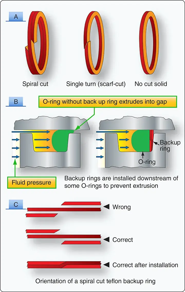 |
| Figure 2. Backup O-rings installed downstream |
Gaskets
Gaskets are used as static (stationary) seals between two flat surfaces. Some of the more common gasket materials are asbestos, copper, cork, and rubber. Asbestos sheeting is used wherever a heat resistant gasket is needed. It is used extensively for exhaust system gaskets. Most asbestos exhaust gaskets have a thin sheet of copper edging to prolong their life.
A solid copper washer is used for spark plug gaskets where it is essential to have a noncompressible, yet semisoft gasket. Cork gaskets can be used as an oil seal between the engine crankcase and accessories, and where a gasket is required that is capable of occupying an uneven or varying space caused by a rough surface or expansion and contraction. Rubber sheeting can be used where there is a need for a compressible gasket. It should not be used in any place where it may come in contact with gasoline or oil because the rubber deteriorates very rapidly when exposed to these substances. Gaskets are used in fluid systems around the end caps of actuating cylinders, valves, and other units. The gasket generally used for this purpose is in the shape of an O-ring, similar to O-ring packings.
Seal Materials
Most seals are made from synthetic materials that are compatible with the hydraulic fluid used. Seals used for MIL-H-5606 hydraulic fluid are not compatible with Skydrol® and servicing the hydraulic system with the wrong fluid could result in leaks and system malfunctions. Seals for systems that use MIl-H-5606 are made of neoprene or Buna-N. Seals for Skydrol® are made from butyl rubber or ethylene-propylene elastomers.
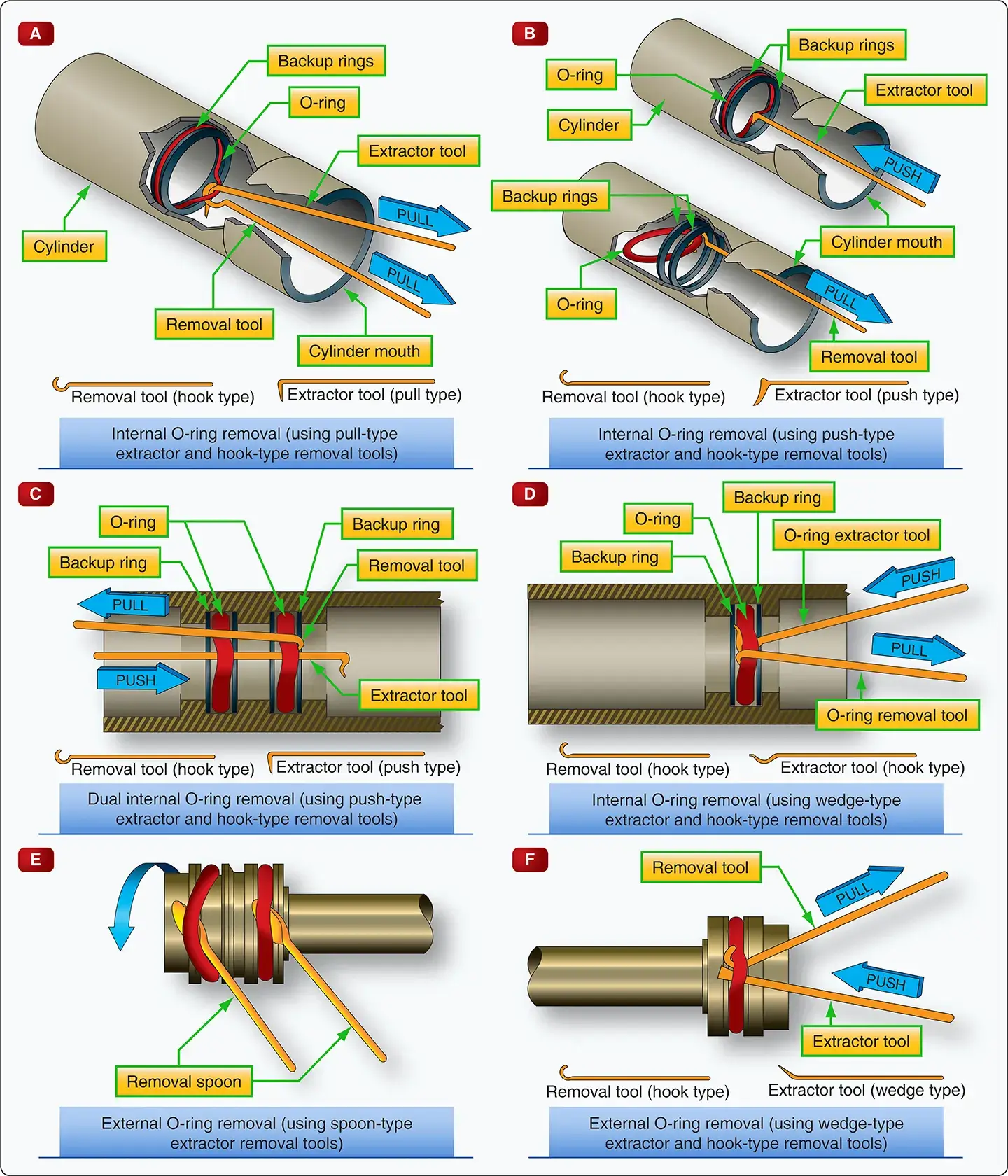
O-Ring Installation
When removing or installing O-rings, avoid using pointed or sharp-edged tools that might cause scratching or marring of hydraulic component surfaces or cause damage to the O-rings. Special tooling for the installation of O-rings is available. While using the seal removal and the installation tools, contact with cylinder walls, piston heads, and related precision components is not desirable.
After the removal of all O-rings, the parts that receive new O-rings have to be cleaned and inspected to make sure that they are free from all contamination. Each replacement O-ring should be removed from its sealed package and inspected for defects, such as blemishes, abrasions, cuts, or punctures. Although an O-ring may appear perfect at first glance, slight surface flaws may exist. These flaws are often capable of preventing satisfactory O-ring performance under the variable operating pressures of aircraft systems; therefore, O-rings should be rejected for flaws that affect their performance. Such flaws are difficult to detect, and one aircraft manufacturer recommends using a four-power magnifying glass with adequate lighting to inspect each ring before it is installed. By rolling the ring on an inspection cone or dowel, the inner diameter surface can also be checked for small cracks, particles of foreign material, or other irregularities that cause leakage or shorten the life of the O-ring. The slight stretching of the ring when it is rolled inside out helps to reveal some defects not otherwise visible.
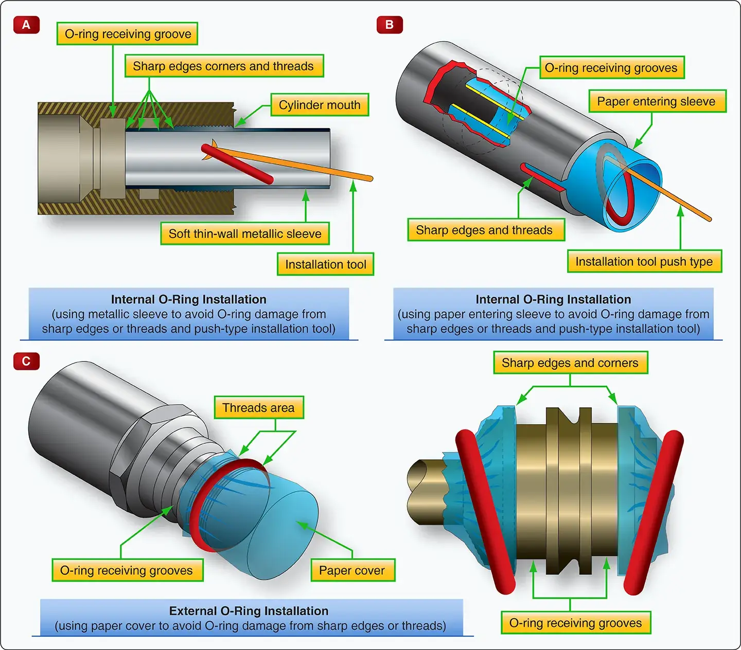
After inspection and prior to installation, immerse the O-ring in clean hydraulic fluid. During the installation, avoid rolling and twisting the O-ring to maneuver it into place. If possible, keep the position of the O-ring’s mold line constant. When the O-ring installation requires spanning or inserting through sharply threaded areas, ridges, slots, and edges, use protective measures, such as O-ring entering sleeves, as shown in Figure 3-A.
 |
| Figure 3. O-ring installation techniques |
After the O-ring is placed in the cavity provided, gently roll the O-ring with the fingers to remove any twist that might have occurred during installation. [Figure 4]
 |
| Figure 4. More O-ring installation techniques |
Wipers
Wipers are used to clean and lubricate the exposed portions of piston shafts. They prevent dirt from entering the system and help protect the piston shaft against scoring. Wipers may be either metallic or felt. They are sometimes used together, a felt wiper installed behind a metallic wiper.